
Numerical hydrodynamic analysis liquid dynamometer for ground run and aircraft piston engine tests
Journal: Siberian Aerospace Journal @vestnik-sibsau-en
Section: Aviation and spacecraft engineering
Article in issue: 2 vol.27, 2026.
Free access
During designs of new internal combustion engines (ICE), modernizing existing ICEs, tuning of fuel systems and ignition systems, the use of dynamometric braking devices provides significant assistance. Such devices can also be used when individually tuned stock internal combustion engines. Many types and designs of such devices are known, including mechanical, electrical and hydrodynamic variants. If an engine torque measuring element is provided in the design of the braking devices, such braking devices are called dynamometers. Most dynamometers are significant in size and weight and are designed for testing, running in and tuning engines with a maximum power of at least 80 hp. and operating speeds of no more than 5000 per minute. Dynamometer stands are also known for high-speed sports engines that take energy from the wheel of a vehicle. The use of dynamometers with rotating elements having a large moment of inertia leads to large errors in tuning. For piston engines of UAVs with a relatively small power of 5-60 hp with operating speed range 4000-10000 per minute the most promising is the use of hydrodynamic braking devices of test and rolling benches. Compared to other devices, they are characterized by smaller dimensions, cost and a wide range of absorbed power. The work includes the design of a liquid dynamometer for testing and tuning the internal combustion engine of an unmanned aerial vehicle with a capacity of up to 100 hp. Optimal geometric parameters of hydrodynamic brake were selected. A three-dimensional solid model of a liquid dynamometer was simulated. A numerical hydrodynamic analysis was carried out with a fixed stator and a movable rotor completely filled with working fluid.
Short address: https://sciup.org/148333986
IDS: 148333986 | UDC: 629.7.03 | DOI: 10.31772/2712-8970-2026-27-2-316-323
Text of the scientific article Numerical hydrodynamic analysis liquid dynamometer for ground run and aircraft piston engine tests
Internal combustion engines (ICEs) for unmanned aerial vehicles (UAVs) require tuning on ground test benches. Most often, this tuning is carried out using an air propeller. Neverthteless, the use of air propellers does not provide necessary precision for tuning. High-quality tuning reqires a braking device that allows the engine to be operated across its entire operating speed range, typically from 2,000 to 7,500 revolutions per minute, at various throttle positions ranging from 0° to 90°. Various types of dynamometer braking devices are listed in [1; 2]. For piston engines in UAVs with a relatively low power output of 5–60 hp, the most promising approach is the use of hydrodynamic braking devices on test and run-in benches. Compared with other devices, they are characterised by their smaller size, lower cost and a wide range of power absorption. The operating principle of this type of brake is based on the resistance offered by the fluid to the movement of a rotor rotating within it (Fig. 1). The rotation of the rotor causes the working fluid to transfer energy. The fluid transfers this energy to the vanes of the stator, which is mounted on the rotating shaft. Water can be used as working fluid and is the most commonly used option. When the brake is in operation, the volume of water passing through it must be proportional to the power being absorbed. The temperature of the water at the outlet of the device must be below 50–70 °C in order to prevent scale formation and cavitation. The water enters the centre of the device and, after passing through the chambers in the stator and rotor, flows out of the housing via the drain hole.
By measuring the torque acting on the stator and the rotor speed, we determine the engine’s power output. The braking moment can be easily adjusted by increasing or decreasing the amount of fluid in the rotor.
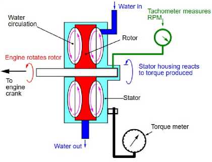
Рис. 1. Принцип работы гидродинамического нагружающего устройства и фотография готового изделия DYNOmite производства компании Superflow, США [2]
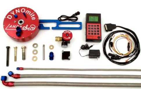
Fig. 1. Schematic water brake on a dynamometer and a photograph of the finished DYNOmite product manufactured by Superflow, USA [2]
Braking devices described in Soviet and Russian literature are designed for use with powerful, lowspeed engines. The authors of this paper have designed and calculated a hydrodynamic brake for testing and tuning piston internal combustion engines with a power output of up to 100 hp.
In [3], the calculation of the hydrodynamic brake was carried out using the SolidWorks Flow Simulation computer-aided design software; however, the geometry of the vanes was overly simplified. In [4], the authors conducted a study into the effect of the shape of the working cavity of a hydrodynamic retarder on braking efficiency. Various studies of hydrodynamic brakes were carried out in [5–12].
Modelling of a hydrodynamic brake
In order to design a device with the correct dimensions and correctly shaped vanes, threedimensional modelling of the rotor and stator was carried out using the SolidWorks modelling system (Figs. 2 and 3); and a computational fluid dynamics analysis was performed using SolidWorks Flow Simulation .
The dimensions of the rotor and stator impellers were initially determined by a series of calculations in a spreadsheet using the formula (1) proposed by B. A. Gavrilenko for a power output of 30 hp at 3000 rev/min [13]. The performance characteristics of the brake with the known geometry are shown in Fig. 4.
D = 2*
Mmp
3.5*10 ( - 5) * γ *[1 - ( r 1 / r 2 ) 5 ]* n 2
where Mmp = 716.2* N/n = 716.2*30/3000 = 7.16 kgm.
As a result, a rotor impeller with a diameter of 220 mm and a thickness of 16 mm was developed, featuring six milled pockets 7.4 mm deep. Six similar milled cavities have been machined into the stator halves. The stator halves feature an inlet for cold working fluid, an outlet for heated fluid, and two drain holes to prevent overfilling and excessive pressure within the brake.
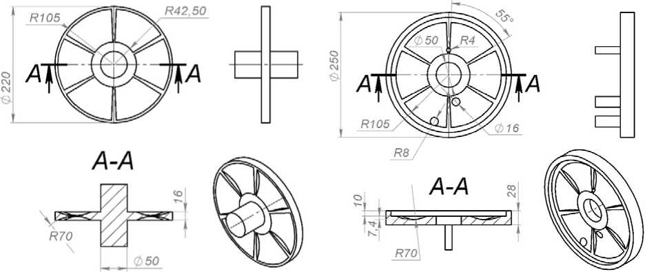
Рис. 2. Чертежи ротора (слева) и статора (справа)
Fig. 2. Rotor (left) and stator (right) drawings
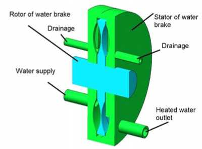
Рис. 3. Сборка гидродинамического тормоза в разрезе
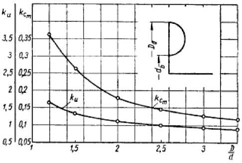
Рис. 4. Характеристики тормоза с известной геометрией [13]
Fig. 3. Assembly of a hydrodynamic brake in section
Fig. 4. Characteristics of brakes with known geometry [13]
Numerical modelling of a fluid dynamometer
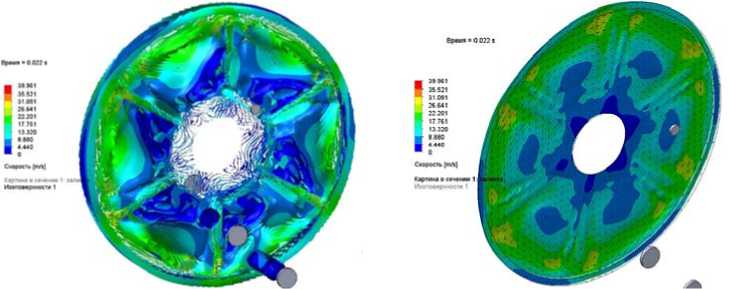
The initial and boundary conditions specified a working fluid (in this case, water) filling 100 per cent of the internal volume. The working fluid is fed into the two orifices of the stator at a rate of 20 litres per minute. For the calculation, the angular velocity of the rotor was set at 3000 rpm. The calculation results at a time of 0.022 s.: pressure and velocity are shown in Fig. 5. The results of the calculation for the hydrodynamic loading device, such as a braking moment and power being absorbed, are shown in Fig. 6.
The SolidWorks Flow Simulation package was used to calculate the braking moment values of the working fluid. To obtain instantaneous braking power, a variable was defined in the Flow Simulation macro language and numerically integrated over the calculation time: Power in hp = ({ SG Moment ( Z ) 4} * 2 * π * {Rotation range 1: Angular velocity: 3.000e+03} / 60) / 735.499.
Figure 6 shows that the instantaneous power being absorbed varies cyclically many times during each rotation of the rotor. Nevertheless, the rotor and crankshaft have a significant moment of inertia, and the fluctuations in the power being absorbed will be considerably smaller. It is recommended to fit a flexible damping coupling between the crankshaft and the brake rotor. The calculations yielded an average braking power of 28.1 hp (ranging from 11.13 to 39.74 per cycle) with the brake fully engaged at 3000 rpm.
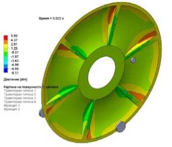
a
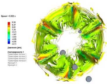
b
c
d
Рис. 5. Результаты расчета гидродинамического нагружающего устройства в момент времени 0,022 с от положения компонентов в сборке: а – поле давлений на поверхности статора; b – изоповерхности давления в рабочей жидкости скоростей жидкости; c – изоповерхности скоростей в рабочей жидкости; d – поле скоростей жидкости в сечении жидкости на расстоянии 8 мм от плоскости симметрии тормоза
Fig. 5. Results of calculation of the hydrodynamic loading device at the time of 0.022 seconds from the position of the components in the assembly: a – the pressure field on the stator surface; b – the isosurface of pressure in the working fluid of fluid velocities; c – the isosurface of velocities in the working fluid; d – the field of fluid velocities in the fluid section at a distance of 8 mm from the symmetry plane of the brake
100 0000000
80 0000000
60 0000000
40.0000000
20.0000000
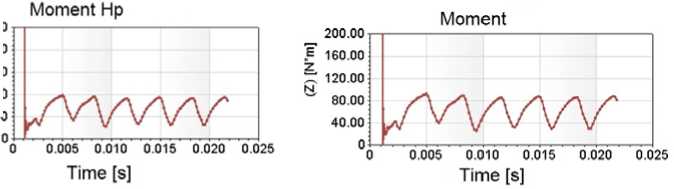
Рис. 6. Результаты расчета гидродинамического нагружающего устройства, тормозящий момент и поглощаемая мощность
Fig. 6. Results of calculation of hydrodynamic loading device, braking moment and absorbed power
To obtain the average braking moment, the following variable was introduced and numerically integrated during the calculation in the Flow Simulation macro language: average ({ SG Moment ( Z ) 4}).
The calculated braking moment is 65.78 Nm.
To reduce the number of calculations, similarity formulas based on tests carried out on a geometrically similar model can be used [14; 15]:
M = Xp D 5 n 2 , (2)
where M is a moment measured by the dynamometer; λ is a moment proportionality coefficient; ρ is the density of the working fluid; D is a rotor diameter; n is the number of revolutions. Since the power is N = Mn , then
N = AD 5 n 3 p , (3)
where A is a power factor, which is constant for geometrically similar machines.
Conclusion
This geometry solves the set problem. As power output depends on the cubic capacity at 7,500 rpm, the maximum power consumption can reach 437 hp, which is excessive for our purposes. As the power output depends on the fifth power of the diameter for 100 hp, the rotor with a diameter of 164 mm is sufficient. In the future, it is planned to design a higher-speed brake, optimise the rotor diameter, use different pocket shapes in the stator and rotor, and optimise the diameter and position of the ports for supplying, removing and draining the working fluid. To improve the uniformity of braking and increase the strength of the device, it is planned to use a greater number of vanes, as well as different numbers of vanes on the rotor and stator.