Removal of Damaged Pipes During Major Repairs of Oil and Gas Wells

Author: Musavi S.
Journal: Бюллетень науки и практики @bulletennauki
Section: Технические науки
Article in issue: 1 т.12, 2026.
Free access
The relevance is determined by the need to solve a number of scientific, practical, and engineering problems related to fishing operations during well workovers. The article provides information on some cases where it is necessary to repeat the operation after completing the fishing work, which should be performed with the lowest possible force parameters and process adjustments. As a result of non-compliance with these requirements, as well as defects formed in the lifting pipes (holes, cracks, wall thickness reduction) due to long-term well operation, the use of standard pipe catchers during emergency operations is further increased. Frequently encountered deformed emergency ends of complex configuration are classified. A classic method for correcting deformed ends is noted, consisting of milling with bottomhole and ring milling cutters and other auxiliary catchers, which can complicate the well situation. The aim of the work is to improve the quality of fishing operations, speed up the extraction of emergency lift pipes with deformed ends of complex configuration, and prevent complications during their extraction from the well. This goal is achieved by implementing an innovative, improved method and design of standard fishing tools adapted to well conditions. The use of the developed straightening and fishing tool-a combined bell consisting of a through bell located at the bottom, which does not function as intended but bends, crushes, and collects the deformed ends in the center, achieving a cylindrical shape and deepening the end of the pipe inward, and a bell located at the top-allows for the removal of the pipe in a single operation by cutting the thread and then screwing onto it. The use of this tool eliminates multi-step operations to correct deformed ends. Depending on the internal diameter of the column and the type and size of the pipes to be extracted, as well as the clamped and sequentially extracted emergency pipes of the first and second rows of lifts with normal emergency ends, by changing the component elements and installing the required number, it is possible to reliably grip and extract them from the well.
Repair, emergency pipes, pipe extraction, well condition
Short address: https://sciup.org/14135577
IDR: 14135577 | UDC: 621.352.6 | DOI: 10.33619/2414-2948/122/12
Демонтаж поврежденных труб с изношенными концами при проведении капитального ремонта нефтяных и газовых скважин
Актуальность работы обусловлена необходимостью решения ряда научно-практических и инженерных задач, связанных с извлечением забойных труб при капитальном ремонте скважин. В статье представлена информация о некоторых случаях, когда необходимо повторить операцию после завершения извлечения забойных труб, которое должно выполняться с минимально возможными параметрами силы и технологическими корректировками. В результате несоблюдения этих требований, а также дефектов, образующихся в подъемных трубах (отверстия, трещины, уменьшение толщины стенки) вследствие длительной эксплуатации скважин, использование стандартных трубоуловителей при аварийных операциях еще больше возросло. Классифицированы часто встречающиеся деформированные аварийные концы сложной конфигурации. Отмечен классический метод исправления деформированных концов, заключающийся в фрезеровании придонными и кольцевыми фрезами и другими вспомогательными уловителями, которые могут осложнить ситуацию в скважине. Цель работы - повышение качества извлечения забойных труб, ускорение извлечения аварийных подъемных труб с деформированными концами сложной конфигурации и предотвращение осложнений при их извлечении из скважины. Эта цель достигается за счет внедрения инновационного, усовершенствованного метода и конструкции стандартных инструментов для извлечения труб, адаптированных к условиям скважины. Использование разработанного выпрямляющего и извлекающего инструмента - комбинированного раструба, состоящего из сквозного раструба, расположенного внизу, который не функционирует должным образом, сгибает, сдавливает и собирает деформированные концы в центре, придавая им цилиндрическую форму, углубляя конец трубы внутрь, и раструба, расположенного вверху; путем нарезания резьбы и последующего навинчивания труба извлекается за одну операцию. Использование этого инструмента исключает многоэтапные операции по исправлению деформированных концов. В зависимости от внутреннего диаметра колонны, типа и размера извлекаемых труб, а также зажатых и последовательно извлекаемых аварийных труб первого и второго рядов подъемов с нормальными аварийными концами, путем замены составных элементов и установки необходимого количества, можно надежно захватить и извлечь их из скважины.
Text of the scientific article Removal of Damaged Pipes During Major Repairs of Oil and Gas Wells
UDC 621.352.6
Oil and gas production wells may fail under certain well conditions, i.e., due to the following reasons: sand plug formation, defects in the production string, as well as in the risers (holes, cracks), and, as a result, their displacement, etc. As a result of the well being taken out of service, a major overhaul becomes necessary. At the beginning of repair work on the well, the lifting pipes are lifted and, in case of sticking, freed. To free them from sand plugs, well packers (if equipped) etc., the stuck string of pump-compressor pipes (PCP) is walked.
As is well known, walking is the periodic application and removal of a certain load to a pipe string, i.e., stretching to the maximum permissible limit and loading below its own weight to cause the tool to move downwards and ultimately upwards [1].
It is also known that an accident during the operation and repair of wells is a violation of the technological process of well operation (repair) caused by the loss of mobility of the pipe string, well equipment, breakage of pipes or rods, or the falling of foreign objects into the well, the removal of which requires special work and tools [2].
In overhaul and drilling of oil and gas wells, accidents occur mainly for the following reasons: violation of repair (drilling) technology; use of faulty tools and equipment; non-compliance with the operating conditions of the tools used; design flaws in equipment and tools [3].
The performance of complex emergency work during overhaul (catching, milling, repairing defects in the column, etc.) by incompetent (less experienced) persons also causes accidents in the well or complications in an emergency situation. The performance of complex emergency operations by less experienced personnel primarily involves fishing operations that do not comply with the technical characteristics of the fishing tool and failure to adjust the power parameters (axial load, rotation speed, etc.) of the fishing operation depending on the well conditions.
Research objects and methodology
When walking, under the influence of repeated alternating (cyclical) stresses, material destruction occurs, called fatigue failure, resulting in the formation of microcracks and, as they grow, the cross-section of the pipe becomes increasingly weakened [4], and finally, the pipe may break (rupture) (in the catchable string - drill string - DS and emergency string - TUBING, DS), which leads to complications in the well. In most cases, when pump-compressor pipes are stuck and cannot be removed whole, they have to be removed in pieces using left drill pipes [5].
When dealing with complex accidents after completing fishing operations, situations may arise where it is impossible to assess whether the operation was successful or not, since there was no change in pressure during the operation, the hydraulic weight indicator (HWI) does not record any additional weight to the tool's own weight, and the tool does not “spring back” when rotated (especially when fishing with cutting tools). This situation is more common when working with MES (special operational tap) fishing taps designed to grab (fish) and retrieve tubing strings ending with a coupling that remain in the well.
It becomes necessary to carry out secondary fishing operations to ensure a positive result, i.e., to repeat the fishing process, and this control fishing operation must be carried out with the lowest parameter values, which must correspond to the maximum design data. If these requirements are not met, the defects (holes, cracks) formed in the lift pipes as a result of long-term operation of the wells are further increased during emergency work on the well (sometimes due to improper operation, incorrect tool selection, or technical impossibility). As a result, the pipes break and rupture. If the cross-section of the end part of the pipe left in the well undergoes a slight change in diameter (ellipsoidality) in the transverse plane as a result of rupture, it can be easily removed using appropriate fishing tools, preferably a fishing bell, which is universal with a certain range of fishing threads. However, if the shape of the end of the emergency pipe differs significantly from the diametric dimensions of the pipe before rupture and destruction, or if it is torn along its length (longitudinal section), serious problems arise with its capture and extraction. During drilling, the tool gets stuck in the open borehole, mainly (more often) due to particles of drilled rock or as a result of crumbling (collapse) of the overlying unstable rock [6].
Due to the large diameter and wall thickness of the drill pipes used, when walking, the load is less than their own weight, i.e., the pulling axial load can be applied at its maximum value. Unlike drilling, in the overhaul of operating wells, since work is carried out in the production column, sticking usually occurs due to jamming of the bottom of the drill string, i.e., technological emergency tools (catching or auxiliary), in most cases, metal particles – pipe fragments, including cut strips, scale accumulated in a certain place of the string, above the emergency end and below – on the catchable string. It should be noted that during major repairs, repair work is carried out on relatively small cross-sections, mainly 168.3 mm, 146 mm, and 140 mm diameter operational columns, and accordingly, small-diameter drill pipes are used, mainly 73 mm and 89 mm, respectively, with the smallest wall thickness. Therefore, when walking, applying the maximum load value below its own weight — the axial load — is not only impractical but also unacceptable. Otherwise, due to the increase in possible and existing cracks, the pipe of the catch column will inevitably rupture for the above reason. The permissible value of the axial load is considered to be within 30-50 kN below the weight of the drill string, depending on the length and type-size of the pipes (and wall thickness) of the string, the gap between them and the production string.
Usually, when a pipe breaks, its end ruptures across the cross section evenly or slightly diagonally. This can be detected after lifting the catch column and examining the condition of the last emergency pipe (provided that no control work has been performed), and there is no need to lower the seal for inspection. After lifting the last emergency pipe, if a rupture is detected, either across the cross section and/or along the longitudinal section, with a significant deviation from the nominal dimensions, the choice of the subsequent method (catching or auxiliary tool) becomes difficult. And lowering the seal may be necessary. After lifting the lead seal, impressions in the form of an incomplete circle or ellipse, arcs (curves) of various lengths and located along diametrical trajectories, as well as point depressions of various diameters and shapes are found on its end face instead of the corresponding diametrical circle.
Discussion of results
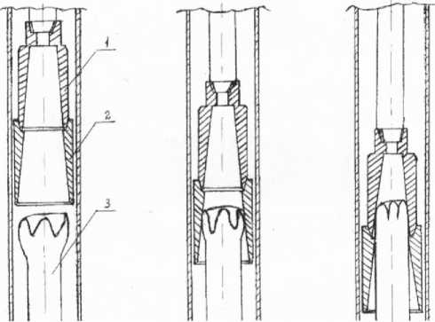
Deformed emergency ends with complex configurations can be classified as follows: one or more opened in the form of a “tongue”; opened in the form of “flower petals”; twisted in the form of a “spiral”; in the form of a “colander” (numerous holes, dents, and cracks from corrosion), referring to the condition of the last pipes coming out of the well, forming a pile of small pieces (debris, fragments, strips, scale) accumulated next to and above the damaged end. Figure 1 schematically shows deformed emergency ends of complex configuration.
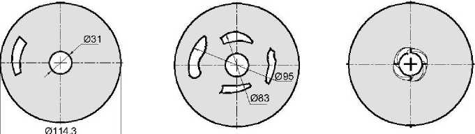
Depending on the configuration of the deformed emergency end, corresponding marks appear on the seal. Figure 2 schematically shows the prints of deformed emergency ends of complex configuration on the seal. In emergency response practice, the most common method of extracting lift pipes with deformed ends from a well, judging by the imprint and after identifying the condition of the pipe end, which is severely deformed, and in order to create normal conditions suitable for gripping with the appropriate standard emergency pipe catching tool, the deformed pipe end is corrected, i.e., processed with different types of milling cutters in the following sequence: end mills, type FZ; ring mills, type FK.
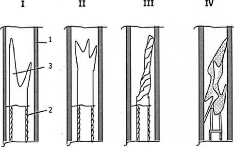
Figure 1. Deformed emergency pipe ends of complex configuration: 1 – operating column; 2 – emergency pipe; 3 – emergency end. I – opened in the shape of a “tongue”; II – opened in the shape of “flower petals”; III – twisted in the shape of a ‘spiral’; IV – in the shape of a “colander”
1 2 3
Figure 2. Impressions of deformed accident ends of complex configuration: 1 – opened in the shape of a “tongue”; 2 – opened in the shape of “flower petals”; 3 – twisted in the form of a ‘spiral’; 4 – in the form of a “colander”
Milling is the most common and widely used method in emergency well recovery, based on cutting metals with various cutting devices [7].
Milling of a stuck object in a well is mainly carried out for the following purposes: to correct the upper end of the stuck object by milling for subsequent capture with a fishing tool; to clean the wellbore by continuous milling of the annular space for subsequent capture with a fishing tool [8].
Designed for milling metal objects in cased and uncased wells, downhole FZ cutters are used in this case to obtain a flat surface across the cross-section of the deformed end of the pipe, i.e., milling to the nominal diameter. FK-type ring cutters are used for milling stuck tubing and casing, which destroy the material (metal objects, cement, sludge) between the wellbore wall and the pipe, i.e., by drilling the annular space, the stuck elements are released [9].
The imprint in the print shows the surface condition and position of the object. Therefore, just below the emergency end, so to speak, “the picture is not clear.” Is there a pipe break in the form of a protrusion below? When fishing with external catchers (in complex accidents, catch bells are more often used), it is very important to know this, especially in the case of a protrusion directed from bottom to top, in which the bell may get stuck during fishing, since the protrusion may bend into the outer surface and enter the gap between the column and the bell, threatening to potentially jam the tool. Therefore, it is mandatory to check or, if necessary, mill (in any case, the work is performed by rotating the tool) the annular space at a distance equal to the pipe's entry into the bell, as this is a characteristic safety feature when fishing. Deformation of the emergency end, “one or more opened in the shape of a ‘tongue’,” occurs when the pipe breaks along its longitudinal section, but mainly when the emergency end of the pipe is repaired.
Deformation of the emergency end in the form of a “tongue” when milling with bottomhole or ring milling cutters of the emergency end occurs in the following well situations:
-
1) in steeply inclined wells or in areas of intense curvature and bending in the wellbore, especially when the deformed end of the emergency pipe is milled by less experienced personnel [10].
The mechanism behind this phenomenon is that when milling in such wells, the emergency pipe leaning against the column is not milled across its entire cross-section. During milling of the emergency pipe leaning against the column, a small part of this pipe is not completely milled, and when milling with a reduction in wall thickness, this part of the pipe is deformed to the size of the inner diameter of the column, resulting in a deformation in the form of a “tongue.” An indicator of this is an increase in torque. It should be noted that, unlike drilling in a major well repair, it is not always possible to use a device that indicates the torque value. In such a possible borehole situation, an experienced specialist feels the jamming and release of the tool during milling and, after milling a short distance with a milling depth mark, be sure to lift the tool; if the tool settles slightly higher, this is a sign of “tongue” formation. In this case, milling continues with a change in the milling mode parameters.
-
2) Forced milling with the smallest diameter milling cutters, i.e., at a relatively large distance (clearance) between the pipe and the inner diameter of the column. During repair and restoration work in a well, as a result of external or internal impact on the production column, after operations to restore compromised integrity, narrowed areas sometimes form in the column [11].
For normal (successful) end milling of metal objects left in the well—73 mm pipes in a column with a nominal diameter of 140 mm, taking into account the smallest total gap between the milling cutter and the casing pipe—the following is required: a bottom hole cutter with an outer diameter of 115 mm (FZ-115) is required, and for successful milling of the annular space of pipes left in the well in a column with a nominal diameter of 168 mm, taking into account the smallest total clearance between the milling cutter and the casing, a ring milling cutter with an outer diameter of 140 mm (FK140-110) is required, which, when lowered, does not pass through the narrowed zone of the production column located above the emergency end.

In such cases, as a last resort, a standard bottom hole cutter (FZ-104) and a ring cutter with smaller outer diameters (FK124-96) are used, which pass through the narrowed zone of the production column located above the emergency end. Only when milling one side of the eccentric or leaning lower part of the production column, the milling cutter deforms it even more, breaks it, in some cases, due to the inability to cover the emergency end with a ring milling cutter, divide the emergency end of the pipe eccentrically located in the production column into parts [12].
In such cases, deformation of the emergency end of a complex configuration, such as a “tongue” or “flower petal” shape, becomes inevitable. Let us consider another case—a different well situation during fishing operations. Above, we considered a well situation in which repeating the fishing process is advisable, and it was noted that it should differ from the previous one in terms of force parameters. The uncertainty is explained by the fact that in the case of catching on the first attempt to change the pressure, it may not have happened for the following reasons: there is a through defect below the catch pipe at a short distance in the emergency pipe column - one or more holes (in most cases, circulation through the emergency pipe shoe is not restored in emergency wells) or during walking – with slight stretching, the weight of the tool on the GIV drops to the tool's own weight, or during turning, by just a few (4-5) turns, the weight of the tool on the GIV drops to the tool's own weight. This is because the caught pipe did not fully open (mostly opened) during the previous operation.
In such a situation, it can be assumed that the captured object “broke away,” i.e., disconnected. Even with indicators during capture (pressure increase, during walking—the smallest stretch withstood a load of 50-60 kN) and in the subsequent operation—turning, in some cases, doubts remain about the successful outcome, since with heavy tools (drill pipe columns), after turning 1-2 emergency pipes, the additional weight is negligible compared to the weight of the tool, so it is virtually impossible to record the additional weight using the GIV. There is a need for secondary fishing operations to ensure a positive result. It is not uncommon for the last pipe to have a coupling (the coupling of the lower pipe of the remaining emergency end) after the emergency pipes have been turned and lifted. When catching pipes with non-release type pipe clamps with a flat-wedge grip TV (internal pipe clamp) and TN3 (external pipe clamp), in case of uncertainty, and when performing control work for gripping during axial load landing, the coupling of the lower pipe deforms (cuts, opens along the diameter, breaks) the nipple end of the lower emergency pipe.
This situation occurs particularly often when removing emergency high-seal pipes with VAM couplings with a reduced coupling diameter. In such a coupling, the diameter of the coupling is significantly smaller than that of pipes according to GOST and API standards (the diameter of the coupling is 73 mm, while the diameter of tubing according to these standards is 89 mm, and the corresponding size with a VAM coupling is 81 mm) [13].
During test fishing, the nipple end of such a pipe deforms the coupling end of the pipe lying below. In such cases, deformation of the emergency end, such as a “flower petal” shape, becomes quite possible. In the event of capture (seizure) on the first attempt, in case of uncertainty, the control capture operation is performed by a competent specialist using the lowest values of the parameters described above. Otherwise, the captured pipe may deform the emergency end (thread or body) located at the bottom of the pipe. When landing, the end of the captured pipe most likely lands on the edge of the end of the emergency column pipe (always in inclined wells). Depending on a number of well parameters (depth, depth of the beginning of the inclination and its maximum value, location of intense curvature and deflection of the wellbore, etc.), the axial load (straightening) of a pipe with a flat-wedge grip can be 50–100 kN or more due to the presence of rust; the inner surface of the pipes may be covered with scale, i.e., a narrowing of the inner diameter. As a result, the gap between the inner diameter and the pipe puller rod is reduced [14].
In such cases, during control fishing after lowering the pipe, landing must be carried out with flushing and with the rod entering with a slight rotation of the tool. When slowly lowering with rotation, the end of the pipe is centered with the emergency end of the pipe left at the bottom, and the nipple end enters the coupling end or vice versa. An indicator of this position is an increase in pressure, as the ends are joined. In this case, the threaded part at the ends is definitely worn down by friction, but there is no deformation in the form of cuts, breaks, or outward bending. Naturally, this applies to cases where there is an acceptable gap between the diameter of the rod and the inner diameter of the production column, i.e., the use of a centering device is not required. Therefore, in the above case, when working with MES-type catch taps, the unscrewed coupling also slightly wears the thread of the nipple end of the lower emergency pipe, rather than deforming its body.
As a result of non-compliance with these rules, the emergency end is deformed and requires additional operations to restore it to a condition suitable for subsequent catching operations. Deformation of emergency ends twisted into a “spiral” occurs when the pipe string is released by walking the clamped string in combination with rotating it with a rotor (“rotor knock-off”).
During emergency work, if an emergency tool (catching tool, auxiliary tool) is found to be jammed, the first thing to do is to move the tool around, periodically using rotor rotation, i.e., turning the drill string to the right (or left, depending on the direction of the connecting thread of the drill lock, the pipes used) at a certain load on it to the calculated permissible safe number of revolutions, depending on the permissible torque of this type and size of pipes, taking into account the wall thickness, strength group, and length of the string. Then, under the action of the formed “spring,” the string rotates in the opposite direction. After performing several operations to cause the tool to move downwards and ultimately upwards, and if no positive result is obtained, the tool is rotated by the rotor.
This process is very lengthy and continues until a certain time, i.e. until a positive result is obtained, which is that the output from the grip is fixed with each application.
As noted above, when walking, under the influence of cyclic stresses, material destruction occurs, called fatigue failure.
There comes a moment when, when striking with the rotor, the number of revolutions in the opposite direction (“spring”) decreases and at some point, after several revolutions, stops abruptly.
After lifting the column, the end of the last pipe is twisted and stretched. It is quite possible to grab the twisted and stretched emergency end remaining in the well with a suitable bell, but it is not possible to extract the emergency pipe from the well, since at a certain required load with rotation for catching, the end twists even more (the twisting continues below), and in the best case, a small broken twisted part of the pipe is extracted (Figure 1-3). Deformation of damaged ends in the form of a “colander” — numerous holes, dents, and cracks — occurs as a result of corrosion. This condition can be identified by the condition of the last pipes coming out of the well. When the tool is moved, as well as after milling, relatively fragile broken fragments, pipe strips, including decomposed fragments in the form of scale, accumulate above the emergency end and nearby as a result of corrosion. The existence of these fragments is evidenced by the fact that after each fishing operation and reversal, there are tight spots. To clean up the broken fragments and pipe strips that have accumulated near and above the accident end, there are standard catchers, such as “spiders” and milling cutters-magnets [15].
When using them, some of these fragments can be removed from the well, but during operation they deform the end even more, and in a volume no less than that removed, breaking off new pieces. Therefore, their use is ineffective. Since 73 mm tubing is most often used in the lower part of the lifting pipe structure (first row), it is these pipes that are subject to deformation and sticking during operation and repair of wells [16].
Considering that the end of the damaged pipe is the body, let us consider the use of possible standard fishing tools in this well situation. The use of a K85-64 non-passable type fishing bell, which has a practical fishing thread range of 82÷67 mm, is not possible in this case due to the openness of the end (Figure 1, 2), as it exceeds the upper limit of this range (85...95 mm). When using it, not only does the recovery fail, but the end is further deformed. The K100-78 type bell has the ability to grip in this open range, but it is possible to recover the body of a 73 mm pipe. Other relevant wedge-type internal (TV-73, TVM-73) and external (TNZ-146, TNO 116-73 with an external diameter of 116 mm and 140 mm, their use is technically impossible) pipe catchers also fail to catch and retrieve the pipe, and the degree of deformation of the end increases. The use of universal operational or drilling taps (MEU, MBU) is not even considered in this case, and their use is unacceptable. When fishing with these standard retrievers, complications in the wellbore (tool sticking) may increase, ultimately leading to a significant increase in repair time and, in some cases, loss of productive formation as the complexity in the wellbore increases. To extract the above-mentioned deformed emergency ends of complex configuration, the author proposed a catching tool that eliminates auxiliary milling work to obtain a suitable end condition for gripping (depending on the conduct and nature of milling, as well as impressions on the reinforced cutting and abrasive part, sometimes it is necessary to repeat the process and remove the print) and extract the emergency pipe in one operation (run). As is known, there are two types of catch bells: ordinary K-type bells (non-passable) and KS through bells [17].
It is also known that a through bell is designed for catching without a coupling or broken end of an emergency pipe with subsequent capture by cutting threads on the outer surface of the locks or couplings of the underlying pipe [18].
They are manufactured with a funnel thread at the bottom and a pipe thread at the top for connecting the receiving pipe. The proposed catching tool consists of two parts, i.e., a combination of two bells: a non-passable K85-64 and a passable KS100 bell (Figure 3).
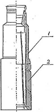
Figure 3. Combined bell type KK: 1 – bell K85-64; 2 – bell KS100
In this case, since the object being caught is a 73 mm pipe, the type and sizes are selected accordingly. To connect the receiving pipe, there is a 102 mm (101.6 mm) pipe thread on the upper part of KS100. The K85-64 bell at the bottom has the same thread for the funnel. The standard (according to GOST 26-02 -1275-75) bell K100-78 with a lifting capacity of 850 kN has an outer diameter of 122 mm, i.e., it can be used in a 146 mm operating column and at larger diameters with the use of centering devices. The KS100 bell also has the same outer diameter [19].
To enable its use in a 139.7 mm (conditionally 140 mm) column, the author proposed reducing the outer diameter to 114.3 mm. This was motivated by the fact that at the bell's entry point, the wall thickness is 7 mm, and at the catch range, at the point of contact (contact) at a diameter of 89 mm ( (89 mm NPT, BT (drill pipe) or 73 mm NPT coupling)), it is at least 12 mm, and accordingly, at a diametric size of 73 mm, it is about 20 mm. Given that, in order to determine the tensile load on the fishing tool, the weight of the drill pipe string is subtracted from the weight of the load on the sling hook, in contrast to drilling, major repairs mainly use operational derricks with a lifting capacity of 100-125 tons, and taking into account that during emergency operations, the use of 73 and 89 mm drill pipes, whose permissible tensile strength does not exceed the limit above this lifting capacity, when walking, the load on the fishing tool (bell) does not exceed 40-50 tons, i.e., much less than the passport indicator. Based on the above, it can be concluded that during fishing, when using the maximum axial tensile force, the safety factor has a multiple value, i.e., the safety of the tool (drill string) is fully ensured.
As noted, the KK100-64 combined bell consists of: the K85-64 bell and the KS100 bell. The purpose of the K85-64 bell remains unchanged. In this design, the function performed by the KS100 bell differs from its direct purpose. The principle of operation of the KK100-64, which has a catch thread in the range of 100–64 mm, is as follows: the deformed emergency end of a complex structure (in the form of “flower petals,” “tongue”) is first processed by the KS100 bell, by rotation and a certain load, as a result of bending, crushing and gathering the deformed ends in the center, achieving a cylindrical shape and deepening the end of the pipe inward, i.e., by inserting it from above into the K85-64 bell to the corresponding nominal diameter of the 73 mm pipe body and grip, cutting the thread by screwing, and extracting the emergency pipe in a single operation [20].
Figure 4 schematically shows the operating sequence of a KK-type combined bell. Unlike fishing with a conventional bell, the first stage of the operation when using a combined bell is to assemble the broken open end of the pipe using a through bell 2 (KS100) to obtain and restore the nominal cross-section for fishing. By flushing and slowly lowering (Figure 4, stage 1), the depth of the broken end 3 is fixed and the landing point of the load within 3-5 kN is marked (measured) on the drive drill pipe (DDP).
1 2 3
Figure 4. How the combined bell works: 1 - K85-64 bell; 2 - KS100 bell; 3 - deformed emergency end of complex design (in the shape of “flower petals”)
The tool is lifted at least 2 m and it is determined whether there is any tightening and the weight of the fishing string is specified. Continuing flushing, the tool is lowered by rotation to a depth of more than 10-15 cm from the fixed landing point, with short breaks, rotation is stopped and the tool is checked for “spring”. The purpose of this operation is to identify the placement of the instrument in deformations in the form of a “tongue” or “flower petal,” i.e., whether it is located in the area of the fracture with the largest cross-sectional area, since the possibility of the “tongue” passing behind the instrument cannot be ignored. If there is no “spring,” it is necessary to fix this location on the VTB. The tool should be lifted by a certain amount and the operation should be continued again, increasing the rotation speed (number of rotor revolutions) of the tool. Due to the increase in rotation speed, the gap between the bell and the inner wall of the production column is practically non-existent, and it becomes impossible for the “tongue” to pass behind the tool. By rotating and lowering the tool with a slight load (5 kN), after 50-60 mm of travel, i.e., after the end of the pipe has entered and passed through the bell entrance, by reducing the rotation speed and according to the more sensitive scale (“Werner”) GIV, an operation is performed to collect the deformed end in the center and deepen the end of the pipe inside the bell. Continue the operation, gradually increasing the load to 10 kN and then gradually increasing the load to 20-30 kN as the tool “returns” to its own weight, as observed on the device. The main signs of restoration to a cross-sectional area close to the nominal size (bending, crushing, and gathering in the center of the deformed end) are an increase in the bell entry distance, which is determined by the mark on the VTB, an increase and then cessation of the “spring,” and, with an increase in load at this moment, a return to the previous position of the pointer on the device, i.e., an increase in the weight of the column to its own weight (Figure 4). In addition, there is a slight increase in the circulation pressure of the flushing fluid depending on the state of the end collection.
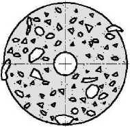
As the distance between the corrected end and the combined bell increases, i.e., as the upper end of bell 1 enters, the second stage is performed—the operation of catching the emergency pipe (Figure 4, stage 3). After capture, the degree of tool attachment is determined depending on the condition of the emergency pipes (meaning the condition of the previously extracted pipes). In the first stage of operation with a combined bell, there are undoubtedly elements of working with a ring cutter. Unlike ring cutters (which have an internal cylindrical shape), the combined bell has the ability to collect in the center (by bending, crushing) due to the internal conical shape of the through bell, which is part of the combined bell. As the distance between the emergency end and the bell increases, the repaired part of the pipe takes on a conical shape. Due to the increase in the contact area with the non-passable bell, a more complete and reliable catch of the emergency pipe is achieved. Figure 5 shows a 73 mm pipe with a tongue-shaped emergency end, assembled as a roll, after processing, gripping, and extraction from the well using a combined bell (Figure 1, 2).
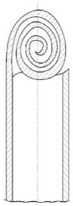
Figure 5. Assembled emergency end in the shape of a “tongue” after removal from the well
In 140 mm (5 ½”), 146 mm (5 ¾”), 168.3 mm (6 5/8”) and having an even larger diameter of operating columns, for extracting severely deformed ends 48, 60, 73, 89, 114 mm tubing, by changing the components (depending on the outer diameter, the range of the bell's catch thread), as well as by installing the required number and collecting them, high-quality catching is ensured in a single lowering and lifting operation. The following types and sizes of combined bells are used for this purpose:
-
1. KK 85-52 (KС 85-69 x K 70-52)
-
2. KK 85-40 (KС 85-69 x K 58-40)
-
3. KK 100-52 (KS 100-79 x KS 85-68 x K 70-52)
-
4. KK 100-40 (KS 100-79 x KS 85-68 x K 58-40)
-
5. KK 115-64 (KС 115-94 x KС 100-79 x K 85-64)
-
6. KK 115-40 (KС 115-94 x KС 100-79 x KС 85-68 x K 58-40)
-
7. KK 125-64 (KС 125-106 x KС 100-79 x K 85-64)
-
8. KK 125-40 (KС 125-106 x KС 100-79 x KС 85-68 x K 58-40)
In another well situation, with a normal termination (coupling, nipple), there is a great need for the use of a combined bell. When extracting the stuck 73 mm pipes of the first row of lifting pipes and the 48 mm pipes of the second row (or flushing pipes stuck during flushing) in a 139.7 mm production column, an error (inaccuracy) is possible in determining the depth of the emergency ends of the 48 mm and 73 mm pipes in the column, due to the fact that the ends of these pipes are located very close to each other after the last fishing, or a change in the depth of the emergency ends is possible for the following reason – the sand between them is soft, and in the previous fishing operation with a turn, the extracted 48 mm pipes came out of the sand plug with tension and rose up a certain distance, that is, it is unknown which end is on top. In this case, to determine the emergency end, the seal is lowered. After determining the 48 mm end at the top, when working with a catching tool to extract a pipe of this type and size—with rotation and a certain load for gripping, as mentioned above, due to the softness of the sand plug, this pipe moves down and reaches the 73 mm end of the pipe. For this reason, the gripping operation is not successful. In this case, the combined bell KK 100-40 (KS 100-79 x KS 85-68 x K 58-40) is an indispensable tool, as it has the ability to grip both the coupling and nipple of a 73 mm pipe and the coupling and nipple of a 48 mm pipe, i.e., ultimately, regardless of which end is higher in the column, the result of the catch is positive and eliminates the need to lower the seal.
It was noted above that, as a result of corrosion, pipes are subject to deformation in the form of numerous holes, dents, and cracks and, after milling, relatively fragile broken fragments, pipe strips, including decomposed small fragments in the form of scale, accumulate above the emergency end and nearby. It was also noted that the use of catch “spiders” and magnetic milling cutters (FM) is inappropriate in this case. The inappropriateness, first of all, lies in the fact that when working with them, new pieces break off from the damaged end in a volume no less than those extracted from the well. Secondly, it is practically impossible to extract broken FM pipe strips, since the catch is made by contact with the upper cross-section (surface), which is many times smaller in area than the longitudinal surface. Even if they are caught, during lifting, accompanied by vibration and jolts when the pipes are released, their “flight” is quite likely due to weak grip. Modern “spiders” also have disadvantages in this well situation, which is the incomplete closure of the catch basket, caused by one of the debris pieces getting stuck in the catcher's tentacles. To this end, the use of a combination bell, which has the ability to collect fragile broken debris and pipe strips of various lengths, widths, and configurations in a single pass, makes it possible to extract numerous broken pieces.
In such well conditions, the combination bell is operated in the following order. By rotation and initially the smallest axial thrust load (settling) (operating mode parameters described above), pipe fragments are captured and fed into the lower bell, and as they descend, due to the decrease in the diametric size of the inner conical surface, these fragments are compressed, then fed into the upper bell, which has an even smaller diametric size of the inner conical surface, and the accumulation continues. The ends and surrounding surfaces are held in place by engaging them in the catch thread along the entire longitudinal section and between themselves. At the VTB mark, after fixing the full engagement in the bell located above, the axial load is gradually increased. During operation – deepening, the indicator (sign) of their compression into a pile, i.e., accumulation, is first a decrease in weight and, within a short time, a restoration of the initial weight, determined by the GIV pointer reading. By the end of the process, with the pressure increasing to the limit, flushing stops.
After lifting, removing these fragments from the bell is difficult, i.e., not easy. There are cases when, during accumulation, it is possible to grab the end of the emergency pipe at the same time. Taking into account the eccentric location of the pipes or in the event of an emergency, the end leans against the wall of the production column, it is important to have a centering device for mutual orientation between the catching tool and the object being caught in the well. For this purpose, the KK body, namely the lower KS, is designed with a cutout. Since the early 2000s, the combined bell has been successfully used in all oil and gas production departments, in the repair of virtually all emergency wells, as confirmed by numerous implementation reports.
Conclusion
-
1. When performing complex emergency operations during major well repairs, one of the causes of accidents in wells or complications in emergency situations is the performance of these operations by incompetent (less experienced) personnel who do not take into account the actual well conditions, which involve adjusting the power parameters of the fishing operation.
-
2. Deformed emergency ends of complex configuration are classified as follows: one or more opened in the form of a “tongue”; opened in the form of “flower petals”; twisted in the form of a ‘spiral’; pipes in the form of a “colander”;
-
3. The origin of the formation of deformations of complex configuration accident ends has been analyzed;
-
4. In the practice of repairing emergency wells, when a severely deformed pipe end is detected, in order to create suitable conditions for subsequent capture with the appropriate standard catching tool, these ends were processed in sequence with bottomhole and ring cutters, which further increased the degree of deformation due to the fragile, broken state of the end face and slightly below the emergency end of the pipes;
-
5. The through bell, which is part of the combined bell, does not work as intended; its principle of operation is similar to that of a ring cutter. Performing work by the nature of the grip - by rotation and a certain load, due to bending, crushing of the deformed ends, further deepening and due to the internal conical shape (unlike the ring cutter), it collects them in the center until a cylindrical shape is achieved;
-
6. As the distance (depth) of the emergency end entering the impassable bell increases, the repaired part of the pipe takes on a conical shape and, as a result of the increase in the contact area with the bell, a more perfect and reliable catch of the emergency pipe is achieved;
-
7. The developed straightening and catching tool—a combined bell consisting of a through bell located at the bottom, having an inner conical surface of the catching thread larger than the nominal diameter of the pipe—is used to bend, crushing and gathering of the deformed ends in the center, achieving a cylindrical shape, deepening the end of the pipe inward, and a bell located at the top, having an inner conical surface of the catching thread corresponding to the outer diameter of the pipe by cutting the thread - the pipe is extracted in one operation by screwing it on;
-
8. To enable the use of a 140 mm column, the outer diameter of the bells included in the combined bell (K100-78 and KS100) is manufactured to order by PO Azneft, and 114.3 mm in design;

-
9. The design and composition of the combined bell can be changed, depending on the internal diameter of the column and the type and size of the pump and compressor pipes that need to be removed, with a severely deformed end, by changing the components of the combined bell and installing them in the required quantity and assembling them;
-
10. The combined bell has a very wide range of applications and, in addition to classified emergency ends (clause 2) of complex configuration, it is also used for clamped and sequentially extracted emergency pipes of the first and second rows of lifting pipes with normal ends (coupling, nipple), in a 140 mm production column;
-
11. Combined bells have been used repeatedly and successfully in all emergency wells of oil and gas production departments.
