Study on The Novel Transient Bus Protection Based on Morphological Top-bottom-operator

Author: Hongchun Shu, Yuetao Dai, Xincui Tian
Journal: International Journal of Intelligent Systems and Applications(IJISA) @ijisa
Article in issue: 3 vol.3, 2011.
Free access
A novel transient component bus protection based on mathematical morphology is presented in this paper, which takes the morphological max top-bottom-operator of current traveling wave to fast distinguish the bus internal fault from the external fault. The method is based on the principle that the high frequency component of transient traveling wave caused by bus external fault will be attenuated by the bus capacitance but the traveling wave caused by bus internal fault changes slightly. Simulation is carried out with the electromagnetic transient simulation software PSCAD/EMTDC, the result verifies the bus protection is reliable and accurate. The novel bus protection also can treat lightning failure or lightning disturbance happened on transmission lines as bus external fault, without malfunction.
Bus protection, mathematical morphology, top-bottom-operator, current traveling wave, lightning
Short address: https://sciup.org/15010180
IDR: 15010180
Text of the scientific article Study on The Novel Transient Bus Protection Based on Morphological Top-bottom-operator
Published Online May 2011 in MECS
The digital protection has been largely applied in China since 90’s of last century. However, the traditional digital bus protection is mostly based on industrial frequency component, the anti-CT saturation ability is poor and the low action speed couldn’t meet the rapid development of the power system increasingly [1-4]. New ultra high speed bus protection algorithm based on fault transient component is proposed by many scholars, which could avoid the impact of CT saturation, transition resistance, load current, system oscillation and other factors. It’ll overcome the disadvantages of traditional protection to a certain extent and improve the speed and the sensitivity of bus protection. So the new bus protection based on fault transient component has practical research significance [5-8].
The transient traveling wave is produced when fault happens and will propagate along the transmission lines. When bus external fault occurs, the transient high frequency component flowing through bus will be attenuated by the bus capacitance [9]. That is to say, the
Footnotes: 8-point Times New Roman font;
Manuscript received January 1, 2008; revised June 1, 2008; accepted July 1, 2008.
Copyright credit, project number, corresponding author, etc.
high frequency component included in current signal decreases and the gradient of waveform will get down. But the high frequency component caused by the bus internal fault won’t be attenuated and the waveform changes slightly. According to these different characteristics of the current waveform under bus fault and bus external fault, the criterion to discriminate bus fault is proposed.
Mathematical morphology (MM) is developed from set theory and integral geometry and is widely used in the areas of image processing, machine vision, pattern recognition and so on [10]. It’s a kind of nonlinear analysis method in time domain entirely and could avoid conversion between time and frequency. It has good realtime performance, rapid speed and high noise inhibiting ability [11].
This paper presents a novel bus protection based on mathematical morphology, which takes the max morphological top-bottom-operator of current traveling wave to distinguish bus fault from bus external fault. Since reported that 90% of the line faults are caused by lightning and lightning has an important influence on the relay protection [12], the behavior of different faults including lightning stokes are analyzed in this paper. Amount of simulations are carried out with the electromagnetic transient simulation software PSCAD/EMTDC. The results verify that the novel transient bus protection could identify the bus fault in many cases and treat lighting failure or lighting disturbance happened on transmission lines as bus external fault, the operation characteristic is excellent.
-
II. Morphological Top-bottom-operator
The basic idea of mathematical morphology is to use a “probe” called structure element to collect the information of signal, and useful information is obtained to make characteristic analysis by moving the structure element on the signal constantly [13].
The basic operation of Morphology as follow:
Dilation operation:
( f ® g )( x ) = max { f(x - y ) + g(y ) } . (1)
Erosion operation:
( f © g )( x ) = min { f ( x + y ) - g i y ) } . (2)
Where f ( x ) is a one-dimensional signal, g ( x ) is the structure element, ® is the dilation operation symbol and © is the erosion operation symbol.
Open operation and close operation are shown as follow:
f o g — f © g ® g . (3)
f • g = f ® g © g . (4)
anyone of the modulus after this transformation could be taken to identify all kinds of failure and the protection malfunction won’t happen. Then the open operation and close operation are taken for a modulus in order to get the max top-bottom-operator.
I a
в
I
2 - 3 I b
- 3
Where o is the open operation symbol, • is the close operation symbol.
Top-hat operator which is used to detect the wave peak of signal is defined as bellow:
Th ( f ) = f - ( f o g ) . (5)
Bottom-hat operator which is used to detect the wave trough of signal is defined as bellow:
Where I a , I b , I c are phase currents. 1 0 , I a , I e are 0, a , в modulus respectively.
Let MTB 1 ~ MTBn be the max top-bottom-operator of each line connected to bus. The maximum value of MTB 1 ~ MTBn is Max( M ) and the sum of the rest is Res( M ) . If the equality (9) holds, it must be bus internal fault, else it is external fault happened on line.
Bh ( f ) = f — ( f • g ) . (6)
Max top-bottom-operator is expressed as:
M ( f , g ) = max(| Th ( f )|,| Bh ( f )) . (7)
Max( M ) о — < 1 .
Res( M )
M reflects the maximum value of the transformation TB after open operation and close operation.
In this paper, semicircular structure element whose radius is 4 is used in morphological open operation and close operation.
The scheme of the bus is mainly divided into three types: signal bus, double bus and bus with one and half breaker. The criterion in (9) is used directly for signal bus scheme while double bus scheme or bus scheme with one and half breaker is treated as two independent bus bars.
The flowchart of this new bus protection is illustrated in Fig. 2.
IV. Electromagnetic Transient Simulation
-
III. Protection Criterion and Scheme
The fault additional network is shown as Fig. 1, where C M is the equal capacitance of bus, the value is 0.002~0.15 μF. In Fig. 1(a), when bus fault occurs at F 1 , the traveling wave propagates from bus to bilateral lines and won’t be attenuated by the bus capacitance, so the current traveling wave detected on each line is mostly similar and contains abundant peaked wave.
When line fault occurs, the traveling wave propagates along the fault line and then refract to non-fault lines, as shown in Fig. 1(b). The current traveling waves on nonfault lines are still similar, but their sum is less than the wave of fault line, because the transient high frequency current flowing through bus is attenuated by the bus capacitance. According to this, the protection criterion is proposed.
The current traveling wave is decoupled after taking new phase-model transformation as (8) shows, because
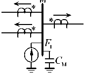
(a) Bus fault
Figure 1. Fault additional network.
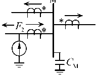
(b) Line fault
The simulation system is show in Fig. 3, this is a bus with one and half breaker. The level of the bus voltage is 500 kV, the level of the source voltage is 220 kV, and the ratio of the transformer is 220/500 kV. MOA is metal oxide lightning arrester, CT and PT represent current transformer and voltage transformer. F 1 is the bus fault and F 2 is the line fault. The simulation sampling frequency is 50 kHz and the data window is 5 ms.
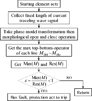
Figure 2. Flowchart of bus protection based on morphological topbottom-operator.
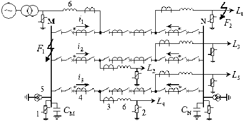
1 – b us moa, 2 – l ine moa, 3 – ct of line protection, 4 – ct of bus protection, 5 – pt, 6 – w ave trapper
Figure 3. Wiring diagram of 3 2 bus.
In Fig. 3, the protection of M bus is consisted by the transient current traveling wave of i 1 , i 2 and i 3 obtained from the CT.
-
A. Single Phase Grounding Fault
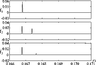
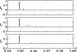
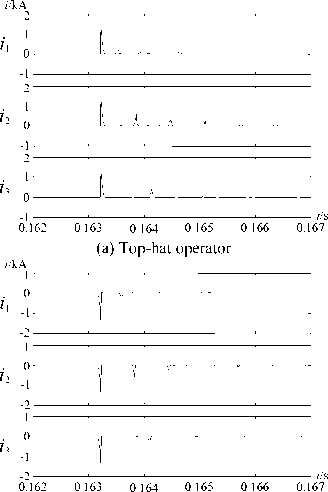
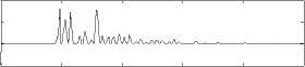
The fault type is A phase metallic grounding failure (AG) and the fault initial angle is 90°. When fault occurs on M bus, the waveforms of the current traveling wave on each outgoing line are shown in Fig. 4, the result of tophat operator and bottom-hat operator are shown in Fig. 5.
See from Fig. 5, the max top-bottom operator is 1.390, 1.389, 1.389 respectively, and e is calculated to be 0.5. This result meets the criterion of bus fault shown in (9), so the bus protection will act to trip.
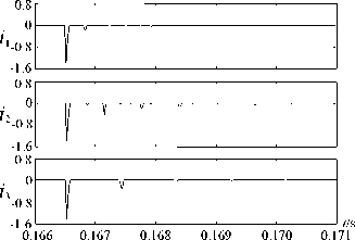
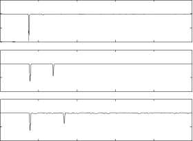
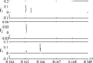
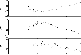
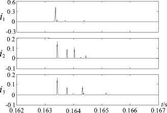
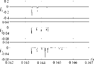
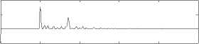
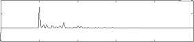
The simulation result of the line fault occurred at F 2 where 50 km away from the bus is illustrated in Fig. 6. The top-hat and bottom-hat operator result are illustrated in Fig. 7.
In Fig. 7, the max top-bottom operator is 0.0745, 0.0252, 0.0253 respectively, and then e = 1.48, the result doesn’t meet the criterion of bus fault, so it is judged to be external fault and the bus protection wouldn’t act.
-
B. Phase to Phase Fault
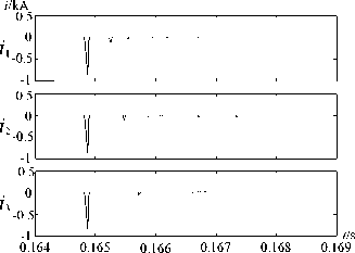
When the bus failure happened at F 1 is A phase to B phase failure (AB), the fault initial angle is 60° and the fault transition resistance is 50 Ω, the simulation result is shown in Fig. 8, and the top-hat and bottom-hat operator result are illustrated in Fig. 9.
See from Fig. 9, the max top-bottom operator is 0.8835, 0.8833, 0.8835 respectively, and e = 0.5. This result meets the criterion of bus fault, so protection will act.
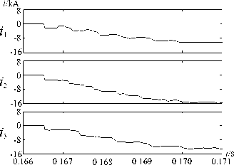
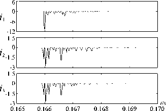
Figure 4. Current traveling waves of bus fault (AG, R=0, θ =90°).
i /kA
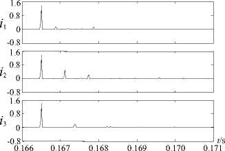
(a) Top-hat operator
i /kA
(b) Bottom-hat operator
Figure 5. Top and bottom-hat operator of bus fault (AG, R=0, θ =90°).
i /kA
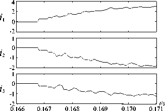
Figure 6. Current traveling waves of line fault (AG, R=0, θ =90°).
i /kA
(a) Top-hat operator i /kA
0.04
0 i -10.04
-
- 0.08
0.02
i
-
- 20.02
-0.04
0.02
i
-
- 30.02
-
- 0.04
0.166 0.167 0.168 0.169 0.170 0.171
-
(b) Bottom-hat operator
Figure 7. Top and bottom-hat operator of line fault (AG, R=0, θ =90°).
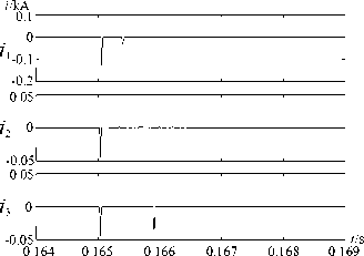
If the fault occurred at F 2 , the result is shown in Fig. 10, the top-hat and bottom-hat operator are shown in Fig. 11.
As illustrated in Fig. 11, the max top-bottom operator is 0.128, 0.044, 0.044 respectively and e = 1.45, the result doesn’t meet the criterion of bus fault, so it judged to be external fault and the bus protection wouldn’t act.
-
C. Three Phase Fault
The initial angle of three phase fault (ABC) is 30° and the fault transition resistance is 200 Ω.
The waveforms of bus fault are illustrated in Fig. 12, the top-hat and bottom-hat operator result are illustrated in Fig. 13. The simulation result of line fault is shown in Fig. 14, the top-hat and bottom-hat operator result are shown in Fig. 15.
In Fig. 13, the max top-bottom operator is 1.373, 1.354, 1.356 respectively and e = 0.507. This result meets the criterion of bus fault, so it is judged to be bus fault and the bus protection will act.
As Fig. 15 shows, the max top-bottom operator is 0.4156, 0.1654, 0.1654 respectively and e = 1.26, the result doesn’t meet the criterion so the bus protection wouldn’t act.
-
D. Results of Different Fault Type
0.164 0.165 0.166 0.167 0.168 0.169
When the fault angle, fault transition resistance or fault distance is different, the partial simulation results are demonstrated in Tab. 1, Tab. 2 and Tab. 3.
All the above simulation results reveal that the novel transient bus protection based on morphological topbottom operator could act correctly in various fault conditions and the reliability is high.
V. Lightning Strokes
In the literature, most studies regarding lightning strokes are for insulation or over-voltage studies, few studies are about the effect of the lightning on transientbased protection algorithms. Since lightning strokes can sometimes cause similar transient behaviors as line faults, the research of lightning on transmission lines is necessary [13].
For lightning disturbance like strikes on tower without back-flashover or strikes in center of the ground wires without failure, the generated transient traveling waves coupled to the conductors of three phases are similar to i/kA
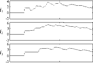
Figure 8. Current traveling waves of bus fault (AB, R=50Ω, θ =60°).
i /kA
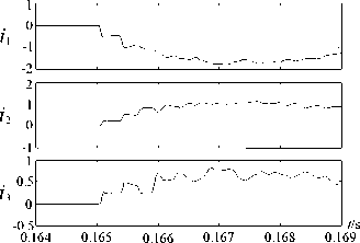
Figure 10. Current traveling waves of line fault (AB, R=50Ω, θ =60°).
i /kA
(a) Top-hat operator
(a) Top-hat operator
(b) Bottom-hat operator
Figure 9. Top and bottom-hat operator of bus fault (AB, R=50Ω, θ =60°).
(b) Bottom-hat operator
Figure 11. Top and bottom-hat operator of line fault (AB, R=50Ω, θ =60°).
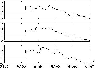
Figure 12. Current traveling waves of bus fault (ABC, R=200Ω,
θ =30°).
(b) Bottom-hat operator
Figure 13. Top and bottom-hat operator of bus fault (ABC, R=200Ω, θ =30°).
i /kA
0.162 0.163 0.164 0.165 0.166 0.167
Figure 14. Current traveling waves of line fault (ABC, R=200Ω,
θ =30°).
each other. The modulus after the phase-model transformation shown in (8) are extremely small, it leads to no-action of protection starting element. So condition of protection malfunction doesn’t exist.
But for shielding disturbance or lightning failure on transmission lines such as shielding failure and back striking failure, the generated transient traveling wave will propagate from the line under lightning stroke to the bus and then reflect to normal lines. The feature of the i/kA
(a) Top-hat operator i/kA
(b) Bottom-hat operator
Figure 15. Top and bottom-hat operator of line fault (ABC, R=200Ω, θ =30°).
TABLE I.
R esult O f D ifferent F ault A ngle (AG, R=50Ω)
|
Fault Position |
9 /° |
M TB1 |
M TB2 |
M TB3 |
ε |
Identification |
|
90 |
0.567 |
0.564 |
0.566 |
0.502 |
||
|
60 |
0.555 |
0.554 |
0.555 |
0.500 |
||
|
F 1 , bus |
45 |
0.532 |
0.530 |
0.530 |
0.502 |
s < 1 , |
|
M |
30 |
0.266 |
0.265 |
0.265 |
0.502 |
bus fault |
|
10 |
0.121 |
0.120 |
0.120 |
0.504 |
||
|
5 |
0.014 |
0.011 |
0.012 |
0.609 |
||
|
90 |
0.306 |
0.112 |
0.111 |
1.372 |
||
|
60 |
0.195 |
0.078 |
0.077 |
1.258 |
||
|
F 2 , Line |
45 |
0.126 |
0.043 |
0.043 |
1.465 |
s > 1, |
|
30 |
0.073 |
0.032 |
0.031 |
1.123 |
line fault |
|
|
10 |
0.044 |
0.019 |
0.019 |
1.158 |
||
|
5 |
0.017 |
0.007 |
0.007 |
1.214 |
TABLE II.
R esult O f D ifferent F ault R esistance (AC, 9 =60°)
|
Fault Position |
R/Ω |
M TB1 |
M TB2 |
M TB3 |
ε |
Identification |
|
300 |
0.535 |
0.536 |
0.535 |
0.501 |
||
|
200 |
0.784 |
0.784 |
0.783 |
0.500 |
||
|
F 1 , bus |
100 |
1.353 |
1.354 |
1.353 |
0.500 |
s < 1 , |
|
M |
50 |
1.350 |
1.350 |
1.350 |
0.500 |
bus fault |
|
10 |
2.313 |
2.316 |
2.314 |
0.501 |
||
|
1 |
2.861 |
2.864 |
2.860 |
0.501 |
||
|
300 |
0.148 |
0.035 |
0.035 |
2.114 |
||
|
200 |
0.203 |
0.046 |
0.046 |
2.207 |
||
|
100 |
0.224 |
0.083 |
0.083 |
1.350 |
s > 1, |
|
|
50 |
0.240 |
0.086 |
0.086 |
1.395 |
line fault |
|
|
10 |
0.265 |
0.118 |
0.118 |
1.123 |
||
|
1 |
0.289 |
0.127 |
0.127 |
1.138 |
TABLE III.
R esult O f D ifferent F ault D istance (ABG, R=10Q e =45°)
The lightning stroke is represented by a current source of negative polarity, a standard 1.2/50 waveform is used in this paper, where 1.2 μs and 50 μs represent the rise time and the fall time of the waveform.
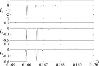
If lightning disturbance happens on A phase line at the point F 2 and the lightning current is 10 kA, the simulation result is shown in Fig. 16, the top-hat operator and bottom-hat operator are illustrated in Fig. 17. The max top-bottom operator is 2.319, 1.024, 1.024
respectively and then £ = 1.132, this doesn’t meet the criterion of bus fault, so it is judged to be line fault and the protection wouldn’t act.
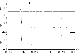
The shielding failure is happened if lightning current is up to 45 kA, and the simulation result is shown in Fig. 18, the top-hat operator and bottom-hat operator are illustrated in Fig. 19. The max top-bottom operator is 11.7, 5.499, 5.499 respectively and £ = 1.064, it is judged to be line fault, so the bus protection wouldn’t act.
It’s easy to see the lightning strokes on line, whether lightning disturbance or lightning failure, would be treated as bus exterior fault and the bus protection is reliable without malfunction.
VI. Conclusions
This paper presents a novel bus protection based on morphological top-bottom operator, which takes the max top-bottom-operator of the current traveling wave to distinguish the bus fault from external fault. The simulation result shows that:
-
1) The protection overcomes the disadvantages of traditional industrial frequency protection to a certain extent and improves the action speed. It has practical
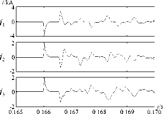
Figure 16. Current traveling waves of shielding disturbance.
i /kA
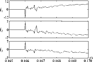
Figure 18. Current traveling waves of shielding failure.
i /kA
(a) Top-hat operator
i /kA
i 1
i 3
2.5
-2.5 8
-4 8
0.165 0.166 0.167 0.168 0.169 0.170
i /kA
(b) Bottom-hat operator
Figure 17. Top and bottom-hat operator of shielding disturbance.
t /s
-4
(a) Top-hat operator
i /kA
(b) Bottom-hat operator
Figure 19. Top and bottom-hat operator of shielding failure.
research significance in today’s increasingly computerized of protection.
-
2) A semicircular structure element whose radius is 4 is used in morphological open operation and close operation. It could detect and abstract the singularity of the signal accurately.
-
3) The operation characteristic of this novel bus protection is excellent, it could act correctly in various fault conditions and the reliability is high.
-
4) The lightning stroke on line, whether lightning disturbance or lightning failure, would be treated as line fault and the bus protection won’t act.
Acknowledgment
Project Supported by National Natural Science Foundation of China (50977039, 50847043, 90610024, 50467002, 50347026) Project Supported by Yunnan Natural Science Foundation of China (2003GG10, 2005F0005Z).
References Study on The Novel Transient Bus Protection Based on Morphological Top-bottom-operator
- J. D. Duan, and B. H. Zhang, “A distributed bus protection using transient traveling wave power directions of transmission lines,” Proceedings of the CSEE, vol. 24, pp. 7–12, June 2004.
- Z. H. Wang, Research and Implementation of Distributed Bus Protection System, Tianjin University, 2001.
- Y. Li, “Study on distributed bus protection system,” Automation of Electric Systems, vol. 23, pp. 45–47, December 1999.
- S. X. Wang, Study on the Transient Protection Principles for EHV Transmission Line, North China Electric Power University, 2005.
- Y. Z. Ge, X. L. Dong, and X. Z. Dong, “A new bus-bar protection based on current traveling waves and wavelet transform (1)-Basic principle and criterion,” Transactions of Chinese Electro Technical Society, vol. 18, pp. 95–99, April 2003.
- X. L. Dong, Y. Z. Ge, and X. Z. Dong, “A new bus-bar protection based on current traveling waves and wavelet transform (2)-Scheme and simulation,” Transactions of Chinese Electro Technical Society, vol. 98, pp. 98–101, June 2003.
- G. B. Zou and H. L. Gao, “Study status and theories of protection for transmission lines based on traveling wave,” Relay, vol. 35, pp. 1–6, October 2007.
- X. Z. Dong, Y. Z. Ge, and J. L. He, “Study status and Prospects of protection based on traveling wave for transmission lines,” Power System Automation, pp. 56–60, May 2000.
- J. D. Duan, B. H. Zhang, and J. F. Ren, “Single-ended transient-based protection for EHV transmission lines basic theory,” Proceedings of the CSEE, vol. 27, pp. 37–43, December 2007.
- Q. H. Wu and D. J. Zhang, “Morphological filtering techniques and applications in protection relaying,” Automation of Electric Power Systems, vol. 27, April 2003.
- X. P. Li and Y. S. Jin, “Accurate Fault Location for HVDC Transmission Line Based on Transient Extraction of Mathematical Morphology,” Modern Electric Power, vol. 24, pp. 20–25, April 2007.
- H. Wang, The Research on Over-voltage Extinction and Protection & Control Strategy for UHV Transmission Line, Tianjin University, 2006.
- H. C. Shu, Electrical Engineering Signal Processing and Applications, Science and Technology Press, 2009.
- X. L. Dong, Y. Z. Ge, and X. Z. Dong, “Effect of Lightning on Protection Based on Traveling Wave,” Proceedings of the CSEE, vol. 9, pp. 74–78, December 2002.
- Y. Z. Ge, Principle and Technology of New Relay Protection and Fault Location, Xi’an Jiaotong University Press, 2007.
- B. Zhang and J. H. He, “Single-ended bus integrated protection based on Karrenbauer transformation,” Relay, vol. 34, pp. 1–4, November 2006.
- D. H. Lu, Y. D. Zhu, and X. Z. Dong, “Study on new bus transient traveling wave protection based on wavelet transform,” Electric Power Automation Equipment, vol. 22, pp. 63–66, August 2002.
- W. Li and Q. Wang, “Extraction of transient character based on the mathematical morphology for distributed bus protection,” Power System Protection and Control, vol. 37, pp. 11–19, January 2009.
- J. Y. Zeng, H. F. Ding, and X. Z. Duan, “Harmonics detection and disturbance location methods based on mathematical morphology,” Proceedings of the CSEE, vol. 25, pp. 57–62, December 2005.
- G. Wang and H. F. Li, “A new bus protection based on transient current spectrum energy,” Automation of Electric Systems, vol. 29, pp. 51–54, March 2005.
