The Identification of Internal and External Faults for±800kV UHVDC Transmission Line Using Wavelet based Multi-Resolution Analysis

Author: Shu Hongchun, Tian Xincui, Dai Yuetao
Journal: International Journal of Intelligent Systems and Applications(IJISA) @ijisa
Article in issue: 3 vol.3, 2011.
Free access
There is a smoothing reactor and DC filter between the inverter and the direct current line to form a boundary in the HVDC transmission system. Since this boundary presents the stop-band characteristic to the high frequency transient voltage signals, the high-frequency transient voltage signal caused by external faults through boundary will be attenuated and the signals caused by internal faults will be unchanged. The wavelet analysis can be used as a tool to extract the feature of the fault to classify the internal fault and the external fault in HVDC transmission system. This paper explores the new method of wavelet based Multi-Resolution Analysis for signal decomposition to classify the difference types fault.
Component, UHVDC transmission line, t boundary unit, Multi-Resolution Analysis
Short address: https://sciup.org/15010184
IDR: 15010184
Text of the scientific article The Identification of Internal and External Faults for±800kV UHVDC Transmission Line Using Wavelet based Multi-Resolution Analysis
Published Online May 2011 in MECS
-
I. Introduction
The first pole of a UHVDC ± 800kV transmission line in the world from Yunnan to Guangdong was put into operation in December 28, 2009. After the commissioning of the second pole and start-up of the entire ± 800 kV system scheduled for 2010, it will become the fundamental transmission link between the southern Chinese provinces of Yunnan and Guangdong. The faults can easily happen in the DC lines because of the extremely long transmission line, high voltage and large capacity. So the fast detection and clearance of faults are important for the security and operation of the UHVDC transmission system [1].
A boundary existing in the DC system presents the stop-band characteristic to the high frequency transient on voltage signals [2], so a boundary protection algorithm based on the significant difference of high-frequency transient voltage caused by external or internal faults is proposed.
The wavelet transform provides a new approach
Footnotes: 8-point Times New Roman font;
Manuscript received January 1, 2008; revised June 1, 2008; accepted July 1, 2008.
Copyright credit, project number, corresponding author, etc.
having capability of analyzing signals simultaneously in time and frequency domain.
In this paper, a hybrid algorithm is proposed to distinguish internal faults from external faults. Most studies regarding lightning strokes are for insulation or over-voltage studies, few studies are about the effect of lightning on transient-based protection algorithms [5].
However, it is found that 90% of line faults are caused by lightning strokes, so lightning strokes have serious influence in relay protection. In this paper, the behavior of different transients consisting of lightning stokes and lightning strokes without causing back-flashover in HVDC system is analyzed using the Wavelet based Multi-Resolution Analysis to extract the fault feature vector of high frequency.
-
II. POWER SYSTEM MODEL
-
A. The frequency characteristics of the transfer voltage ratio
The Power Systems Computer Aided Design (PSCAD) is used for modeling UHVDC system, as shown in Figs.1. The system used here is a ± 800 kV, 5GW, 12-pulse bipolar system. The line model is 1500 km long frequency dependent model and 6 sub-conductors per bundle. The smoothing reactors installed on the DC line side of the rectifier and the inverters are 400mH. The DC filter in this model is three-tuned filter; the relay is set at the point M; the F1 and F2 are the internal faults on the positive polarity and negative polarity respectively. The external faults, F3 and F4, happen between the rectifier and the smoothing reactor.
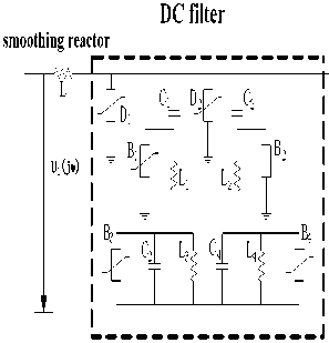
The boundary composed of the smoothing reactor and three-tuned filter is shown in Figs.2. The voltage of the external fault is defined as U 1 . The parameter U 2 presents the voltage which from external faults passes through the boundary. In this paper, The parameters B1, B 2 , B 3 , B 4 (the arresters applied on the DC filters), D 1 (the arrester of the smoothing reactor) and D 2 (arrester of the DC bus) are all named as boundary arresters. The rated voltage of the arresters B 1 , B 2
is 150 kV. The rated voltage of the arresters B 3 , B 4 is 75 kV. The rated voltage of both D 1 and D 2 is 824 kV.
The parameters in the Figs.2 are as follows: L=400 mH, L 1 =39.09 mH, L 2 =26.06 mH, L 3 =19.545 mH, L 4 =34.75 mH, C 1 =0.9 μF, C 2 =0.9 μF, C 3 =1.8μF, C4=0.675 μF.
The transfer function of the boundary is defined as
HQ j о )
Z i (j o )
Z 1 ( j о ) + Z 2 ( j o )
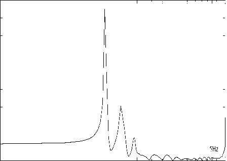
and Z 1 (jω) is the impedance of the DC filter, Z 2 (jω) is the impedance of the smoothing reactor. Figs.3 shows the frequency characteristic of the boundary.
As illustrated in Figs.3, the boundary composed of the smoothing reactor and three-tuned filter can attenuate the high frequency transient caused by external faults. H(jω) ≈ 1 at low frequency (less than 100 Hz) but H(jω)≈ 1 at high frequency (more than 2000 Hz). The curve presents the oscillation of the frequency characteristic, when 1000 Hz < f < 2000 Hz; especially at 600 Hz, 1200Hz and 1800 Hz, H(jω)>>1.
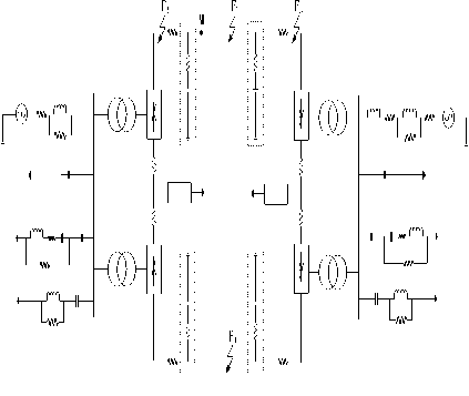
Figure 1. UHVDC ± 800kV system model
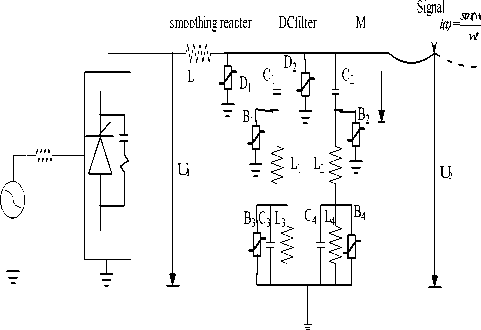
B Sweep characteristics of the boundary element
Consider the regulation of the thyristor rectifier ,
a current source with 20kHz bandwidth inject into the end of the measurement M as sweep signal. as shown in Fig.4.
sin( 2 x 10⁴ x t) 2 x 10⁴ x t
H j o ) = U1- (3)
Form the Figs.3 and Figs.4, You can see that the boundary components has the high frequency stop-band characteristics
DC transmission line
Fighre2. Boundary composed of the smoothing reactor and DC filter
THE FEATURE OF DC LINE FUALT
The process after the fault occurred of the transmission line is divided into three phases: the begging of fault (in the usual sense of the traveling wave process), the transient fault, the fault steady state.
The first is the initial wave phase , the fault additional components discharge by line impedance. The electric and magnetic fields along the line which storage the energy can mutual transform into fault current traveling wave and the corresponding fault voltage traveling wave. The voltage at the measured point depends on the line impedance, the DC voltage value before fault occurred and the physical boundary of the reflection coefficient.
Fighre2. The fault transient after the initial fault phase, this phase is the energy of electric and magnetic fields change into each other. The fault transient components including the amount of the transient fault pulse of DC component and the transient transmission line circuit parameters determine the volatility components. These include transient frequency, energy and information such as fault distance
When a fault after the early transient fault and transient fault, the fault will be stable at steady state. Both sides of the fault current is equal to the setting value of depending on current controller and both sides
| H (jω)|
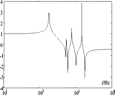
Fighre3. Frequency response characteristic of the boundary of the fault current flows in opposite directions. The rectifier current curve and the inverter side current curve is shown in Figs.4
THE FEATURE OF DC LINE FUALT
The control scheme of HVDC is generally divided into three levels: master control, pole control and bridge control.
The bridge control determines the firing instants of valves and produces desirable pulses [6]. The response time of the first level is about 100 ms, and the response time of the third level is about only 3ms. the control system can not respond on the wave phase. When a fault afte r the first prompt, enter the fault transient process, the control system begins to function. It can be seen that the fault transient process is the result of the fault transient response and control transient response interaction. The function of control system is resulting in lower DC voltage level. as shown in Fig 9.
In this paper, the influence of control system is taken into account on the performance characteristic of the DC line protection, so the sample length is set at 2 ms, at a 100 kHz sample rate to avoid the transient response of control system.
A typical CIGRE DC control system is built in PSCAD / EMTDC, including: rectifier control system for constant current control; inverter side of the control system is mainly for the constant current control, current bias control, set off angle control.
531 1062 3125 6250 12500 20000
Figure 5. A Frequency scanning of closed-loop boundary element
Wavelet transform is possible to extract information in time domain by decomposing the transient signal with short scale of window for high frequency band while with long window scale for low frequency band using scale and contrary to Fourier transform. In this paper Wavelet is used to classify the internal fault and the external fault.
in Fig. 7 αinv firing angle for the inverter side, βinv 、 trigger the lead angle for the inverter side. Unipolar DC transmission line fault transient process, the leg remained normal conduction. With the DC fault current increases, the turn-off angle γ increases. Ignore the off angle measurement of the time,when failure occurs, set off angle control system put into operation immediately, followed by constant current control system in operation, by adjusting the trigger lead angle βinv, reducing the amount of fault current changes. It can be seen from Figure 9, the control system response time is usually 50ms ~ 60ms, after the role of the control system, inverter side of the trigger delay angle αinv stable at nearly 850 or so. Inverter side of the current setting than the rectifier current value by 10%.
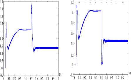
(a) the rectifier side (b) theinverter side Figure 6. The current curve
WAVELET TRASNFORM
Wavelet transform is possible to extract information in time domain by decomposing the transient signal with short scale of window for high frequency band while with long window scale for low frequency band using scale and contrary to Fourier transform. In this paper Wavelet is used to classify the internal fault and the external fault.
MRA (Multi-Resolution Analysis) utilizes DWT as a tool to represent a time varying signal in terms of frequency components. In MRA the original signal is decomposed into several other signals with different scale of resolution.
The decomposition of signal g(t) is in terms of scaling function and wavelet function, which can be
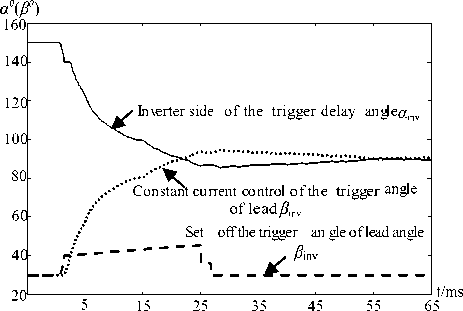
Figure 7. The control system transient response in the inverter side
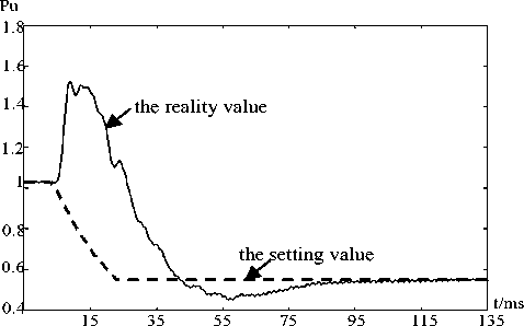
Figure 8. The control system transient response in the rectification side expressed as:
j - 1
g ( t ) = Z j (t - k ) + ZZ d j ( k )2 j 2 Ц 2 j t - k ) (4) k k j = 0
Where the detailed version (high frequency components) of the decomposed signal is generated by the wavelet function wavelet function and the approximation version (low frequency components) of the decomposed signal is generated by the scaling function .
NNNN
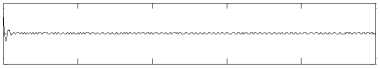
E 1 = Z I d 1 ( k )| + Z I d 2 ( k )| + Z I d 3 ( k )| + Z I d 4 ( k )| (6) K = 1 K = 1 K = 1 K = 1
Where d 1 , d 2 , d 3 , d 4 is the detailed version(high frequency components) and the frequency is 3.125kHz-25kHz.N=500. E 1 is the energy of high frequency.
N
E 4 = Z V1 4 ( k )l K = 1
Where a 4 is the approximation version (low frequency components) E 2 is the energy of low frequency.
K q = E 1 / E 4
-
B. Commutation Failure
Commutation failure is one of the common faults in HVDC system. It will lead the DC voltage decreasing and current increasing at the same time. If taking wrong measure, the continual commutation failure will take place [7].
When the three phase short circuit fault or single-phase ground fault occurs on the inverter side, the bus voltage and current of the three-phase AC system will soon decrease and increase, respectively. These sudden changes may lead to commutation failure. One example is given here to illustrate the result of the commutation failure.
-
C. Lightning Strokes
Lightning can sometimes cause similar transient behaviors as line faults. Three types of lightning strokes are considered here(lighting strikes the tower causing back-flashover, lightning strikes the tower without back-flashover, and lightning strikes directly on the line).The lighting stroke is represented by a current source of negative polarity.
A standard 1.2/50 waveform is used in this paper, where 1.2 μ s and 50 μ s represent the rise time and fall time of the waveform.
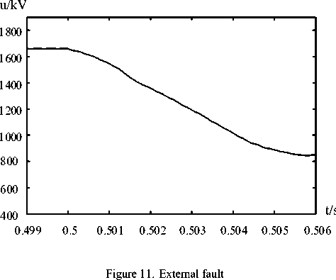
u /kV
BOUNDARY PROTECTION
A. DC Line Faults
Due to the electromagnetic coupling existing between the DC transmission lines of two poles, the Karenbauer transform-based phase-modal transformation is adopted to transform the DC voltage signals to line-model voltage signals. In this paper, the line-model voltage is expressed as:
without control system
-200
-400
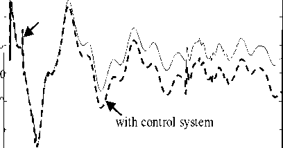
Figure 9. Fault transient response
u 1 m = u + — u -
t/ms 15
In this paper the sampling frequency of 100kHz , the different resolution levels with their frequency bands is shown in Table1.
u/kV
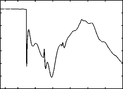
400 t
0.499 0.5 0.501 0.502 0.503 0.504 0.505 0.506
Figure 10. Internal fault
SIMULATION RESULT
k>2 , the internal fault k≤ 2 , the external faul
CONCLUSIONS
A novel boundary protection algorithm based on the smoothing reactor and DC filter between the rectifier and the direct current line to form a boundary which presents the stop-band characteristic to the high frequency transient voltage signals is proposed in this paper. Wavelet transform is used for extracting fault transient information and MRA (Multi-Resolution Analysis) is used to distinguish internal faults from the external faults. A The different factors that affect the performance of protection algorithms are considered, such as transients caused by HVDC control system, lightning strokes, high ground fault resistance and the effect of noise. Traveling wave protection is not subject to the control system; first instant when the fault after fault after fault transient process into the control system begins to function. Can be seen, the process is a transient response and control of transient system, the response of the superposition of two physical processes, ultimately resulting in lower DC voltage level, this is conducive to DC low voltage protection. After 50 ~ 60ms, the two sides of the fault current is equal to the respective constant current controller, respectively, the setting value, the difference is equal to 0.1pu. The role of the control system, making the final two races of the current difference is relatively small, to a certain extent, limit the value differential protection criterion for the size of the whole, and thus can not effectively identify the fault outside the AC side.
The proposed algorithm shows satisfactory performance under various conditions.
The following types of faults with different fault distances and resistances are simulated.
DC line fault types: single line to ground fault (L-G), line to line fault (L-L), line to line to ground fault (L-L-G). (internal and external faults) Fault locations: 1 km, 100 km, 500 km, 1000 km. (only internal faults)
Fault resistance: 0.1Ω, 1Ω, 10Ω, 100Ω.
(internal and external faults)
The signal is sampled at 100 kHz , the fault occurs at 0.505 s. The conditions of commutation failure(CF), lightning strokes causing back-flashover and lightning strokes without back-flashover are also simulated to test the capacity of this protection algorithm . Noise is usually unavoidable during the measurement. White noise with 30 db SNR is added to the DC voltage in this case.
The criterion of external fault and internal fault is follows:
2000 I I I I [ I
0I-------------------------------------------------I-------------------------------------------------I-------------------------------------------------I-------------------------------------------------i1
0 100 200 300 400 500
-500
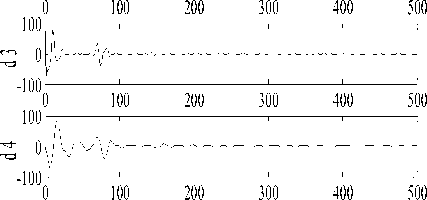
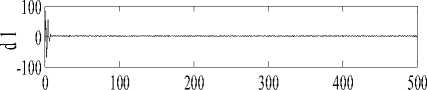
Figure 12. Result of MRA for internal fault
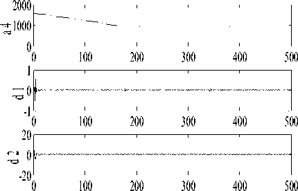

Figure 13. R Result of MRA for external fault
ACKNOWLEDGMENT
Project Supported by National Natural Science Foundation of China (50977039,50847043 , 90610024 , 50467002 , 50347026)Project Supported by Yunnan Natural Science Foundation of China(2003GG10 , 2005F0005Z) .
References The Identification of Internal and External Faults for±800kV UHVDC Transmission Line Using Wavelet based Multi-Resolution Analysis
- Rashmi A. Keswani, “Identification of fault in HVDC converters using wavelet based multi-resolution analysis,” Nagpur, Maharashtra. pp. 954-959, July 2008.
- Zhang Baohui, and Duan Jiandong, “ Development on transient- based protection for transmission lines,” Journal of electric power science and technology, vol. 23, no. 4, December 2008.
- C. N. Bhende, S. Mishra, and B. K. Panigahi, “Detection and classification of power quality disturbances using S-transform and modular neural net work,” Eletric Power Syetems Research, pp.122-128, 2008.
- Xiaolei Liu, A. H. Osman, and O. P Malik, “Hybrid traveling wave/boundary protection for monopolar HVDC Line,” IEEE transaction on power delivery, vol. 24, no. 2, pp. 569-578, April
- XU wenhao, LIAO zhiwei, HUANG shaoxian, and WANG gang, “A model of HVDC control system based on Hybrid petri net,” Transmission and Distribution Conference and Exhibition, Dalia, pp.1-6, December 2005.
- AI Lin, and CHEN Wei-hua, “Reseach on traveling wave protection criterion on HVDC transmission line,” Relay, vol. 31.
- Ai Lin,Chen Weihua. Discussion on line protection of HVDC transmission line[J]. relay, 2004,32(4):61-63.
- Yang Qing,Zhao Jie,Sima Wenxia. Lighting back-flashover performance of the YUN-GUANG UHVDC transmission lines[J]. high voltage engineering, 2008,34(7):1330-1335
- Zhang Yongji, Sima Wenxia, Zhang Zhijin. Summary of the study of tower models for lighting protection analysis[J]. High voltage engineering, 2006,32(7):93-97
- Zhoupeihong, xiumuhong, gudingxie. Study of ± 800 kV DC System Over—Voltage Protection and Insulation Coordination[J].electric power construction, 2007,28(1):12-18
- Zhu Yu,Liang xXu,,Min Yong. Simulation of line protection of HVDC transmission based on PSCAD/EMTDC[J]. modern electric power, 2006,23(2): 35-38
- Cao Jifeng,Wang Gang,Zhang Haifeng. Study on Protection Configuration and Optimization of HVDC Line[J]. SOUTHERN POWER SYSTEM TECHNOLOGY.2008,2(3):26-29
- Zhoupeihong,xiumuhong,gudingxie. Study of ± 800 kV DC System Over—Voltage Protection and Insulation Coordination[J].electric power construction, 2007,28(1):12-18
- Zhu Yu,Liang xXu,,Min Yong. Simulation of line protection of HVDC transmission based on PSCAD/EMTDC[J]. modern electric power, 2006,23(2): 35-38
- Cao Jifeng,Wang Gang,Zhang Haifeng. Study on Protection Configuration and Optimization of HVDC Line[J].SOUTHERN POWER SYSTEM TECHNOLOGY.2008,2(3):26-29
- ZHANG Baohui, HAO Zhiguo, and BO Zhiqian, “Development of relay protection for smart grid(1):new principle of fault distinction,” Electric Power Automation Equipment, vol. 30, no. 1, pp.1-6, January 2010.
- Xiaolei Liu, A. H. Osman, and O. P. Malik, “Hybrid traveling wave /boundary protection for monopolar HVDC line,” IEEE transaction on power delivery, vol. 24, no. 2, April 2009
- D. Naidoo, and N. M. Ijum, “HVDC line protection for the proposed future HVDC system,” 2004 internationl conference on power system, pp.21-24, November 2004.
- HA Hengxu, and ZHANG Baohui, “The study on identification of fault and lightning strokes in boundary protection for EHV transmission lines,” Relay, vol. 31, no. 4, pp.1-5, April. 15, 2003.
- D. Naidoo, and N. M. Ijumba, “A protection system for long HVDC transmission lines,” Inaugural IEEE PES 2005, Africa Durban, pp.11-15, July 2005.
- Luo Haiyun,Fu Chuang. Discussion of the voltage change rate setting value in traveling wave based protection of GGH HVDC line [J]. Southern power system technology, 2008,2(1):14-21
