Using stationary wavelet transform in bch image coding

Author: Seddiki Ali, Djebbari Ali, Rouvaen J.M.
Journal: Техническая акустика @ejta
Article in issue: т.3, 2003.
Free access
This paper propose a novel technique that use efficient image compression based on stationary wavelet transform (SWT) decomposition and Bose-Chauhuri-Hochquenghem (BCH) coding for image transmission over additive white Gaussian noise (AWGN) channel. We know that, discrete wavelet transform (DWT) decomposition suffers a drawback which is the not time-invariant transform, leading to a non-redundant decomposition. This means, even with periodic signal extension, the DWT of a translated version of a signal X is not, in general, the translated version of the DWT of X. In such case, the use of an adequate wavelet transform that restore the translation invariance, appear efficient to give high-quality image reconstruction. Also, BCH coding is a linear block procedure that permits multiple-error bit correction over noisy channel. The idea is to combine efficient image compression gived by SWT decomposition with an exam of the selection of the Bose-Chauhuri-Hochquenghem (BCH) error correction codes applied to the low pass version at different decomposition level. By using BCH(63,45,3) code against the channel degradation, a significal improvement is obtained.
Short address: https://sciup.org/14316210
IDR: 14316210
Использование стационарного вэйвлет-преобразования в БЧХ-кодировании изображений
В данной работе предлагается новая технология использования эффективного сжатия изображения, основанная на стационарном вэйвлет-преобразовании (СВП) и кодировании Бозе-Чаухури-Хохквенхейма (БЧХ) для передачи изображения по каналу с аддитивной помехой в виде «белого» гауссового шума. Известно, что дискретное вэйвлет-преобразование (ДВП) имеет тот недостаток, что оно не инвариантно относительно преобразования времени, что ведет в свою очередь к неполноте представления. Это означает, что при «растяжении» даже периодического сигнала ДВП принятого сигнала X(t), вообще говоря, не равно принятому ДВП сигнала X(t). В этом случае оказывается эффективным использование адекватного вэйвлет-преобразования, сохраняющего инвариантность, с тем, чтобы дать высококачественное восстановление изображения. Также, БЧХ-кодирование есть линейная процедура, которая допускает в шумовом канале передачи корректировку по признаку кратных ошибок. Идея состоит в том, чтобы объединить эффективное сжатие изображения, даваемое СВП разложением с анализом отбора, осуществляемого с помощью БЧХ кодирования, применяемого при выделении низкочастотной составляющей сигнала. Применение БЧХ-кодирования с параметрами (63, 45, 3) позволило добиться значительного улучшения качества передачи, устранив искажения, вносимые каналом передачи
Text of the scientific article Using stationary wavelet transform in bch image coding
Electronic Journal «Technical acoustics»
-
2. DISCRETE WAVELET TRANSFORM
The continuous wavelet transform is by now recognized as a fruitful technique in signal and image processing, whereas discrete wavelet transform or dyadic wavelet transform is often more appropriate for image synthesis. The continuous wavelet transform is defined by the function [5] in equation (1), with the wavelet mother w ( t )
+“
C ( t , a ) = ^ J x ( t ) W I----I , (1)
a
-M where the wavelet family given by

where a is a scale factor affecting the frequency and the amplitude of the signal, т is a time factor localizing the wavelet position in the signal x ( t ) .
Knowing that the wavelet family is characterized by the following property
W( t ) = W (- t )
and using the inverse transform, one can reconstruct the original signal by
x
t —т 1 1 , , --- — d T da .
a I a
If we use a dyadic form, such a = 2 j ; т = k 2 j ; j e N , k e Z , the wavelet family became
Wj, k = 2-j/V(2 j - k ), which form an orthonormal base of the continuous signal space. And equations (1) and (2) became
M
Cj , k = X x n W jk (n) , n = 0
M M
X n H C j W ( n ) , (3)
-
j' = 0 k =-m
where W jk ( n ) are obtained by translates and dilates of the wavelet function w ( n ) , and Cjk represents the discrete wavelet transform coefficients which are the estimation of signal components at ( 2 - j k , 2 j ) in the Time-Frequency plane.
The discrete wavelet transform is the most useful technique for frequency analysis of signals that are localized in time of space. It decomposes signals into basis functions that are dilations and translations of a single prototype wavelet function, equation (3).
Actually, the discrete wavelet transform [6] corresponds to multiresolution approximation expressions. This method permits the analysis of the signal in many frequency bands or at many scales [7, 8]. In practice, multiresolution analysis is carried out using two channel filter banks composed of a low-pass (G) and a high-pass (H) filter and each filter bank is then sampled at a half rate ( 12 down sampling) of the previous frequency. By repeating this procedure, it is possible to obtain wavelet transform of any order. The down sampling procedure keeps the scaling parameter constant (k = 12) throughout successive wavelet transforms so that it benefits for simple computer implementation. In the case of an image, the filtering is implemented in a separable way by filtering the lines and columns.
An example can be illustrated in fig. 1. According to this procedure, the original image can be transformed into four sub-images, namely:
-
• LL sub-image: Both horizontal and vertical directions have low-frequencies.
-
• LH sub-image: the horizontal direction has low-frequencies and the vertical one has high-frequencies.
-
• HL sub-image: The horizontal direction has high-frequencies and the vertical one has low-frequencies.
-
• HH sub-image: Both horizontal and vertical directions have high-frequencies.
-
4. SYSTEM MODEL
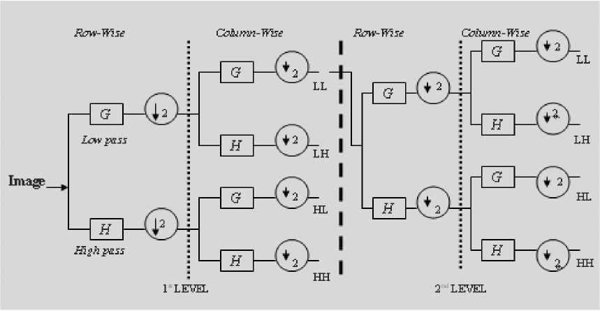
Fig. 1. Two-level discrete wavelet transform
Figure 2 shows the block diagram used in our study. The system consists of stationary wavelet transform compression first step, which leads to a source coding by reducing the size of the original image ( 256 x 256) to an image of size ( 32 x 32 ) using such daubechies wavelet, followed by optimal scalar quantifier (Lloyd algorithm) [10], and Gray coding transformation to form a block of k columns binary message and ( 32 x 32 ) lines.
The second step of the chain, is the BCH encoder, which encode our message to a matrix block using a BCH code ( n,k ), to form a block codeword of n columns and ( 32 x 32 ) lines , with n>k . The length of each codeword is equal to n. A discrete channel is assumed with additive white Gaussian noise. At the reception, a BCH decoder decodes the received coded message followed by Gray decoding and some inverse transformations (inverse quantization and inverse stationary wavelet reconstruction) to form reconstructed image.
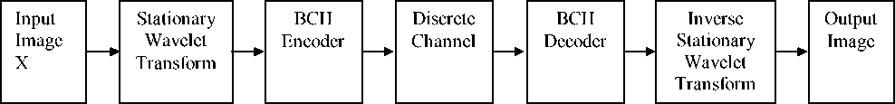
Fig. 2. Block diagram of the BCH image coding
We investigate the performance of our system in a discrete channel model with AWGN . Here, we use the bit error rate ( BER ) as the performance measure for BCH coder; and an image Peak-signal to noise ratio ( Peak-SNR ) [11] as the system performance measure for quality image reconstruction, equation (4), which is the signal to noise ratio based on pixel difference between the original image and reconstructed image:
(
\
PSNR = 10log10
^L X L-^ X SxJ-x y )
V x y J where Lx and Ly are horizontal and vertical sizes of the image, and Sx,y and Sˆx,y represent the intensities of the original and reconstructed pixels, respectively.
After decoding, there is good correction of channel errors using BCH coding. The noise present in the reconstructed images, figures 3-b and 3-c, is due the step of inverse quantization. Using the Lloyd algorithm [11], with arbitrary initial codebook of length equal to 2 q ( q quantization parameter), the quantization index of the input signal is based on this initial codebook and on the decision point partition (partition is a strict ascending ordered q - 1 vector that specifies the boundaries).
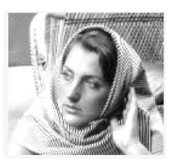
(a) Original Image
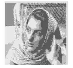
(b) Reconstructed Image: N=3 and BCH(15,5,3), with quantization parameter q=2
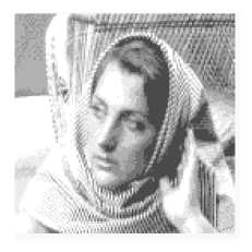
(c) Reconstructed Image: N=4 and BCH(15,5,3) , with quantization parameter q=2
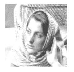
(d) Reconstructed Image: N=3 and BCH (63,45,3) , with quantization parameter q=3
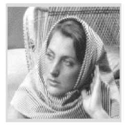
Fig. 3. Reconstructed image after BCH decoding with different stationary wavelet decomposition level and quantization parameter over noisy channel
(e) Reconstructed Image: N=3 and BCH (63,45,3) with quantization parameter q=4
We see that, more is the length of the initial book, more efficient inverse quantization is; and using BCH(63,45,3), a good image quality is obtained fig. 3-d and fig. 3-e. To analyse more these results, tables 1 and 2 gives error rate received code ( BER ) with correlation parameter (between reconstructed and original image) at different decomposition level for BCH(15,5,3) and BCH(63,45,3) respectively. We can see a close relation between the decomposition level N and the used BCH code (63,45,3) .
Table 1. BCH(15,5,3)
|
Level N |
Error rate received code |
Error rate after decode |
Corr |
|
2 |
0.1867 |
0 |
0.9580 |
|
3 |
0.1874 |
0 |
0.9581 |
|
4 |
0.1859 |
0 |
0.9587 |
|
5 |
0.1863 |
0 |
0.9604 |
Table 2. BCH(63,45,3)
|
Level N |
Error rate received code |
Error rate after decode |
Corr |
|
2 |
0.1868 |
0 |
0.9588 |
|
3 |
0.1855 |
0 |
0.9608 |
|
4 |
0.1867 |
0 |
0.9611 |
|
5 |
0.1854 |
0 |
0.9645 |
In fig. 4, the variation of the PSNR at different decomposition level shows that the use of BCH(63,45,3) code, provides a visible performance than BCH(15,5,3) code without necessary further decompositions level.
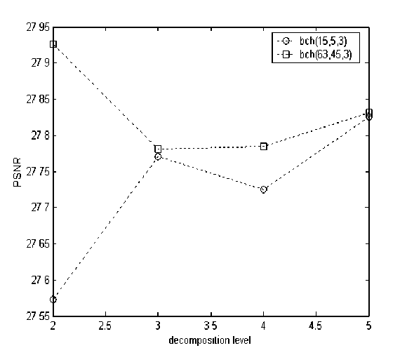
Fig. 4. Received image PSNR against decomposition level
We can see, in fig. 5, a significant improvement in the error rate received code at level N=3 which is less in the case of using BCH(63,45,3) code.
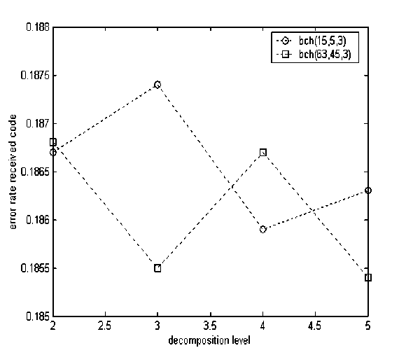
Fig. 5. Error rate received code against decomposition level
The received image correlation, given in fig. 6, shows good correlation parameter when the BCH(63,45,3) code is used at different stationary wavelet decomposition level.
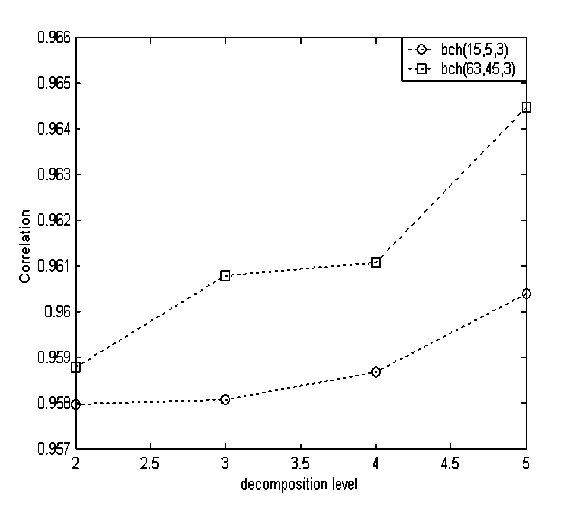
Fig. 6. Image correlation against decomposition level
-
6. CONCLUSION
In this paper, we have investigated the characteristics of the stationary wavelet transform which provides the texture information in images to source coding with BCH codes for channel correction. By preserving invariance by translation in stationary wavelet compression, we have obtained significant improvement in reconstructed images at different level of decomposition. There is a close relation between the number of level and the type of BCH(n,k,t) code. By assuming that channel affects the first bits of the binary sequence message (which are more significant), the selection of the BCH code provides significant improvement when ( N=4, BCH(15,5,3) and N=3, BCH(63,45,3) ).
In perspective of this work, the effect of joint channel estimation by stationary wavelet filtering will be studied.
