
Optimal Control of the Membrane Module Start-Up Mode in the Membrane Distillation Process
Journal: International Journal of Engineering and Manufacturing @ijem
Article in issue: 4 vol.16, 2026.
Free access
The study considers the issue of optimal control of the start-up mode of the membrane distillation process. The aim of the work is to increase the efficiency of controlling the process of concentrating solutions in a contact membrane distillation unit, which will contribute to reducing the cost and increasing the level of energy saving of the process with prior uncertainty and changes in the permeability of the membrane over time. An analysis of various publications has shown that no single approach has been proposed to control the start-up mode of the membrane module of the process. For control purposes, a mathematical model of the dynamics of the membrane distillation process is proposed. The written mathematical model of the contact membrane distillation process is nonlinear with respect to the temperature of the solution at the outlet of the membrane module, which is also included in the equations that take into account the vapor flow through the membrane. With an increase in the temperature of the solution at the inlet of the membrane module, the temperatures of the solution and distillate at the outlet of the membrane module increase nonlinearly. The optimality criterion was the minimum process start-up time in the presence of restrictions on the final solution temperature. The penalty method and the gradient procedure on the second interval were used to change the control in order to reach the specified regime. The solution depends on the value of the weight coefficients of the penalty functions, which allowed reaching the specified regime in the minimum time.
Short address: https://sciup.org/15020582
IDS: 15020582 | DOI: 10.5815/ijem.2026.04.10
Text of the scientific article Optimal Control of the Membrane Module Start-Up Mode in the Membrane Distillation Process
The relevance of the search for optimal control of the contact membrane distillation process lies in the fact that to date, no single approach to controlling the start-up mode of the process has been proposed. Water is of crucial importance for human life and nature. The demand for fresh water is rapidly increasing due to population growth and urbanization, while clean water resources are being depleted. So far, desalination remains the most reliable and practical technology for supplying drinking water. However, all traditional desalination technologies are energy-intensive methods, regardless of their advantages. Therefore, the projected growth of water desalination technology should correspond to the reduction of energy consumption and environmental impact. Today, membrane distillation (MD) technology is trendy and is developing rapidly due to its attractive properties. There is a strong need to develop less
This work is open access and licensed under the Creative Commons CC BY 4.0 License.
energy-intensive and environmentally friendly methods of water purification. One of the sources of replenishment of drinking resources can be desalination of mineralized water. Currently, reverse osmosis accounts for 60% of desalination plants worldwide. An alternative to reverse osmosis is contact membrane distillation (CMD). The process is characterized by internal disturbances, in particular due to concentration polarization. During the transport of solvent through the pores of the membrane, the concentration of the solute near its surface increases, which leads to a number of undesirable consequences. Over time, the control of the CMD process becomes more complicated due to changes in membrane characteristics, such as porosity and thermal resistance. The membrane must be hydrophobic, using common materials, including polypropylene (PP), polytetrafluoroethylene (PTFE) and polyvinylidene fluoride (PVDF). The task was to develop and study the optimal control of the start-up mode of the membrane module in the contact membrane distillation process.
2. Literature Review
Some researchers began to focus on transient modeling and time analysis of MD processes [1-4].
Analysis of various publications showed that the optimal control of the contact membrane distillation process has been fully investigated only with the use of solar energy. The paper proposes an optimal control of direct contact membrane distillation with renewable energy sources, which allows to maximize water desalination by dynamically adjusting the flow rate of the cold stream in response to fluctuations in the inlet temperature caused by solar energy [5]. Other works have solved the problem of real-time optimization for a solar-powered water desalination system and direct contact membrane distillation [6]. This approach is possible in the case of sufficient solar energy. In most cases, regulation occurs by changing the temperature of the solution at the inlet. A comprehensive optimal control system for solar thermal membrane distillation systems is presented, which allowed to increase productivity [7]. The disadvantage of using a “burst-burst” type regulator (or positional regulator) is the high amplitude of fluctuations of the controlled parameter, which does not allow to achieve stable operation of the system.
3. Mathematical model
For control purposes, a mathematical model of the CMD process with lumped parameters was developed, which takes into account the heat transfer through the polymer structure of the membrane and the flow of solvent vapor, which consists of heat capacities [8-11]:
-
- solution channel;
-
- distillate channel.
When creating the mathematical model, the following assumptions were made:
-
1) the membrane is ideal, i.e. hydrophobic with the same pore radius and an intact selective layer;
-
2) the effect of temperature and concentration polarization was not taken into account;
-
3) the change in temperature and concentration along the MM channels was not taken into account;
-
4) the membrane capacity was not considered, taking into account its thickness in comparison with the height of the solution and distillate channels.
The structural diagram of the membrane module (MM) is presented in Fig. 1.
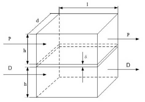
Fig. 1. Membrane module diagram.
The mathematical description of the MM is based on the material and energy flows of the process. The heat balance equation of the MM dynamics:
GpHCpHdpH — kF(dpE — 8ek) — FsJpr
—
G pK c pK d pE ^ p P pK ^ pK
de pE
G dhcdh @ dh + kF(d pK в ок ) + FeJ p r G oK c DK e DK — F dpdecde
dt ’ dd DE
dt ’
Where:
r is the specific heat of vaporization,
J/kg; V Р =V D =Sl is the volume of the solution and distillate channel, m3;
-
ρ РК , ρ DК is the density of the solution and distillate at the outlet of the MM, kg/m3;
c РК , c DК is the heat capacity of the solution and distillate at the outlet of the MM, J/(kg^K); 9 РН , 0DH is the temperature of the solution and distillate at the inlet of the MM, K.
The evaporated solvent is transferred in the pores of the membrane, condensing on the cold surface of the membrane. To calculate the specific mass flow of vapor, the relationship for the case of molecular diffusion was used
_ MDBPpa Рх — Р2(в2)
Jp— 8R9 рд—рЖ)
Where
Jp is the specific mass flow of steam, kg/(m2^s);
M is the molar mass of steam, mol;
-
D ВP is the effective coefficient of mutual diffusion of steam in air, m2/s;
-
p a is the atmospheric pressure, Pa;
-
p g , p х is the pressure of the steam-air mixture on the warm and cold surfaces of the membrane, Pa;
-
p 1 , p 2 is the partial pressure of the solvent vapor on the warm and cold surfaces of the membrane, Pa;
-
θ 1 , θ 2 is the temperature on the membrane surfaces in the solution and distillate channels, K;
R is the universal gas constant, J/(mol·K); θ=(θ РК +θ DК )/2 is the average temperature of the membrane, K; θ PК , θ DК is the temperature of the solution and distillate at the outlet of the MM, K.
The ratio of pressure differences in (2) is represented by the ratio:
Px — P2(d2) Пкр(Рд-Рх)
-------77"V — e*P----=-------- pc — p1(d1) DEPpa where DКP is the Knudsen diffusion coefficient, m2/s;
The linearized energy conservation equations in increments on linear sections were presented in the form а13вРХ + а15вРХ + а16вОХ —
^ 25 d p^ + а^в ^ ак
de ak dt ’
de DX dt ’
where the model coefficients are: solution channel heat balance equation а13
G phcph
У р р рк с рк
а 15
____1 2MD kp (p ^ — P х )eF(r + C pk ^ dk) ' vpppkcpk[ PH PK 8R(e pK + O dkY .
1 _ 2MD Kp (P g — P x )£F(r — С рк в ркУ
F p p PK c PK [ 8R(d pK + в окУ2 .
distillate channel heat balance equation
_ 1 Г _ 2МРКР(рд - рх)sF(r + Cdk0dk}\
VpPdkCdk[ SR(d PK + O dk)2 J
-
1 гмРкАрд-рх^к^кв^
a26 = VpPdkCdk[ GdНCDК k 3R(0Pk + 0dk)2 J
4. Optimal Control
The initial membrane data during simulation are presented in Table 1, and the technological process data are presented in Table 2.
Table 1. Input data for membrane modeling.
|
Parameter |
Parameter designation |
Unit of measurement |
Value |
|
Membrane pore radius |
r |
m |
0,12∙10-6 |
|
Membrane module length |
l |
m |
0,5 |
|
Membrane thickness |
δ |
m |
3,03∙10-4 |
|
Membrane porosity coefficient |
ε |
– |
0,8 |
|
Membrane tortuosity coefficient |
γ |
– |
0,2 |
|
Cross-sectional area |
d |
m2 |
0,025 |
Table 2. Technological process data.
|
Parameter |
Parameter designation |
Unit of measurement |
Value |
|
Solution temperature |
Θ H |
К |
333 |
|
Distillate temperature |
Θ D |
К |
303 |
|
Concentration of salt solution |
b Н |
kg/kg |
0,1 |
|
Solution flow rate |
w Р |
m/s |
0,1 |
|
Distillate flow rate |
w D |
m/s |
0,1 |
|
Diffusion coefficient |
D s |
m2/s |
3,24·10-5 |
|
Vapor flow through membrane |
J w |
kg/(m2 ⋅ s) |
1,188·10-5 |
The task was set to optimally control the start-up mode of the membrane module. That is, to bring the device to a given temperature of the solution at the outlet of the membrane module in the shortest possible time, given the presence of restrictions on the temperature of the solution at the inlet.
The objective function of the task
I = tf ^ min under restrictions 0рк(1^) = 0$ and 9pHmin ^ 0ph ^ 0рнтах where tf is the final moment of time, 0рн min, 0PH max are the minimum and maximum values of the solution temperature at the inlet to the membrane module.
The penalty function method is applied in the gradient method of finding the extremum in the functional space to calculate the control and trajectory when translating the system (4), 0 рн min < 0 PH < 0 PHmax from the state 0РН (0) = 0РН and 0 DH (O) = 0 DHO to the state 3PK ( tf ) = 3 GV for the minimum time.
This problem is solved as a minimum cost function problem [12]
I= t f +~^ 11 [0 PK (t f ) - 0 PK (t f )] + ~S 22 [0 DK (tf) - 0D>k] ^ min
You can take into account restrictions on the control action by introducing a penalty function into the criterion
I = t f + 1 sn ‘^ ( t f ) - c ] 2 + 1 S 22 \oDK ( t f ) - c ] 2 +
+ j [ Q ( в рН max — О рк ( t ) )( ^ РН ( t ) — в РН min ) ] H ( q i , q 2 )*
where H is the Heaviside function, q1 = ® PH max — ^ ph ^ 0
q 1 = в рнЮ — S pHmin ^ 0
Then the Hamiltonian is equal to
H — ( Q pHmax - в рнК ^ рн — S pHmin )H[q 1 >q 2 ] + Х 1 (ацв рк + Оцв рк + ^^ рн ) 2 + ^ 2 (а 21 9 рк + a 22 0DK) (6)
where A 1 (t),A 2 (t) are Lagrange multipliers. The conjugate system has the form
|
dH ^ 1 — —~д0~ — —а 11 ^ 1 — а 21 ^ 2 PK (7) dH ^ 1 — QQ — а 11 ^ 1 a 12 ^ DK |
|
|
Transversality conditions: |
X 1 (t f ) — ^ 11 (9 px (t f^ — 9 px) (8) ^ 2 (t f ) — ^ 22 (9 pK (t f ) — ^ РК ) |
We obtained an expression for ---- дв рн
dH _ tt- = Q(vphmax д^РН
—
29 рн
+ ^ PH min )H(q 1 , q 2 ) + ^^ 1
To determine the final moment of time, the condition ^7 = 0 was used as a criterion for stopping the iterative process.
dt = 0 — 1 + 511(0рк(£/) бРЮ^РК^-р) + $22(9dk max(tf) б^^^К^р) +
Then the optimal control procedure can be described as follows [8].
di0
We choose the initial control 9 PH (t), calculate the trajectory of the system state vector and the derivative —. From di0
the condition ^ — 0 we determine the termination time for the first iteration. With this final time we solve the adjoint equations in reverse time, which are necessary for calculating the increment
\QPH(tA — —k-^ and control 0PH(t) — врН(1) + MpH(t) °dPH
for the next iteration. These calculations continue until the increment Дв рн of the control from iteration to iteration becomes small.
Suppose that the control QPH — врн is chosen as the initial one. We solve the mathematical model of the process in direct time until ^ = 0.
Then the control changes and takes the value в РН = 0 РН . The mathematical model of the process is solved again until the condition ^ = 0 is met.
If the initial control does not coincide with the optimal one and the system does not reach the desired mode, then the conjugate system is solved in reverse time from t f to 0 [13-16]. Then the next value of the control
0рнЮ = бРнЮ + ЫрнЮ = 0°рн(С) -к^ °МрН
This calculation process continues until the specified mode is achieved.
For the solved problem в РН = 65 ° C , в РН = 80 ° C .
5. Materials and Methods
First, we calculated the transition trajectory of the final solution temperature at the minimum input temperature 0 рН = 65 C according to this algorithm (Fig. 2.). The final temperature reaches the level в РН = 64,5 C . Then we change the input solution temperature to the maximum в'РН = 80 ° C (Fig. 2.). The solution temperature value at the membrane module outlet goes beyond the permissible в РН = 78 ° C.
6. Results and Discussion
Since the external point method is used in the penalty method, this is permissible. For the second stage of control, we calculated the conjugate system (7) with transversality conditions (8). We found the control gain and for the new iteration the change in the inlet solution temperature in time. The iterative process of finding the optimal control continues until the outlet solution temperature becomes a given one.
The graph of the change in control and the temperature at the outlet of the membrane module is shown in Fig. 2. and Fig. 3.
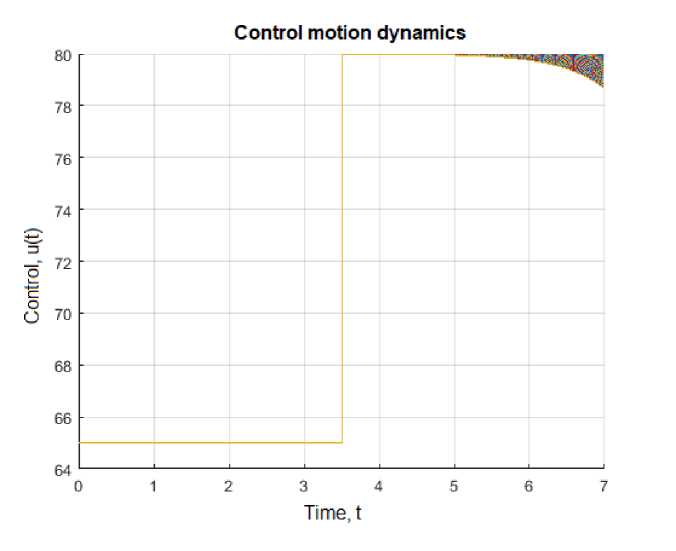
Fig. 2. Temperature control change schedule at intervals.
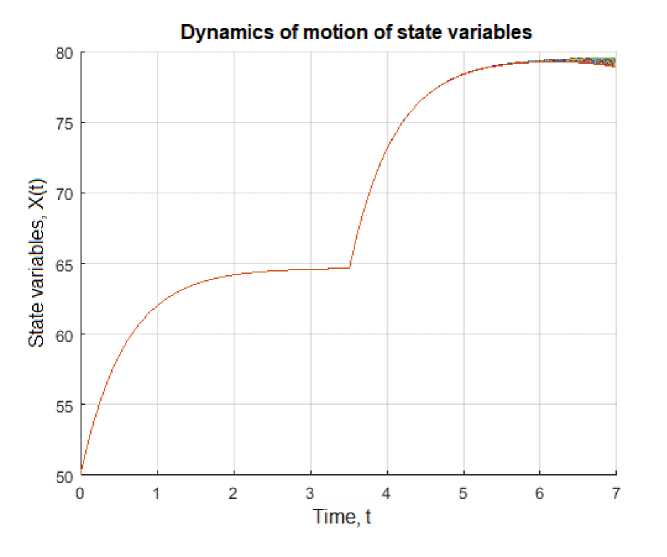
Fig. 3. Graph of change in solution at the module outlet during control stages.
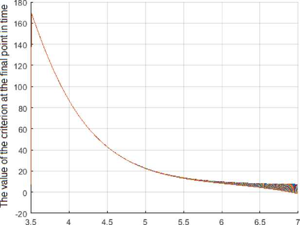
Fig. 4. and Fig. 5. show the graph of the change in the optimality criterion and the graph of the change in the Lagrange multiplier over the control interval.
Time, t
Fig. 4. Graph of changes in the optimality criterion.
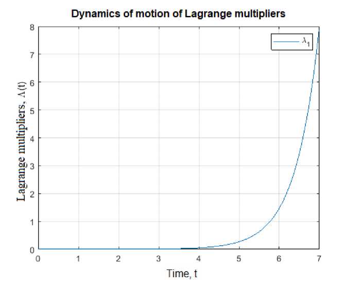
Fig. 5. Graph of the change in the Lagrange multiplier over the control interval.
We investigated the quality of the obtained control for a given system in the minimum time. The solution depends on s and s and k which are determined by trial and error. The problem was solved in 40 iterations, the minimum time for the system to reach the origin is 7.3 s.
7. Conclusion
An algorithm for optimal control of the membrane module start-up mode in the membrane distillation process is proposed. The minimum time for the membrane module to reach the specified mode with a limitation on the outlet solution temperature was chosen as the optimality criterion. The final start-up mode time was entered into the terminal component of the cost function. The penalty method and the gradient procedure were used to solve the problem. The applied algorithm allowed the membrane module to reach the specified technological mode.
All the Declarations and StatementsAuthor Contribution Statement
Lesya Ladieva – Conceptualization, Methodology, Supervision, Writing – original draft.
Roman Dubik – Investigation, Data curation, Formal analysis, Visualization, Writing – review and editing.
Bogdan Korniyenko – Writing – review and editing, Mathematical modeling.
All authors have read and agreed to the published version of the manuscript.
Conflict of Interest Statement
The Authors declared no conflicts of interest.
Funding Declaration
This research received no external funding.
Data Availability Statement
The data that support the findings of this study are from the corresponding author upon reasonable request.
Ethical Declarations
This study did not involve human participants or animals.
Acknowledgements
We sincerely thank the experts for their professional evaluation and valuable recommendations, which have contributed to improving the quality of the experiment and the reliability of its results.
Special thanks to the National Technical University of Ukraine "Igor Sikorsky Kyiv Polytechnic Institute" for providing the experimental facilities.
Declaration of Generative AI in Scholarly Writing
During the preparation of the manuscript, the authors carefully reviewed the content and take full responsibility for the accuracy and integrity of the manuscript.
Abbreviations
Not applicable.
Appendix A\B\C…, with appendix tile
Not applicable.